Application and Research of Steel Sheet Pile Reinforcement Technology in Long Riverbank Excavations
Abstract
Steel sheet pile reinforcement technology is widely utilized in deep excavation projects, particularly in challenging environments such as long riverbank excavations. This paper provides an in-depth scientific analysis of the application of steel sheet piles in such contexts, focusing on their structural stability, interaction with surrounding soil, and performance under varying geotechnical conditions. Through theoretical formulations, finite element modeling, and numerical comparisons, the study evaluates the efficacy of steel sheet piles in ensuring excavation safety and stability. Key aspects, including lateral earth pressure, pile deformation, and soil-structure interaction, are analyzed with supporting formulas and data. The research also compares different pile configurations and reinforcement strategies, offering insights into optimizing design for riverbank excavations.

1. Introduction
Long riverbank excavations, particularly for urban infrastructure projects such as utility tunnels, flood barriers, or bridge foundations, pose significant geotechnical challenges. These excavations are often conducted in water-rich, soft soil environments, where maintaining stability and preventing collapse are critical. Steel sheet piles have emerged as a preferred solution due to their high strength, ease of installation, and ability to provide both structural support and waterproofing.
This study explores the application of steel sheet pile reinforcement technology in long riverbank excavations, emphasizing scientific analysis through theoretical models, empirical data, and numerical simulations. The objectives are to:
- Analyze the mechanical behavior of steel sheet piles under riverbank excavation conditions.
- Develop and validate mathematical models for soil-pile interaction.
- Compare different pile configurations and reinforcement strategies using numerical data.
- Provide design recommendations based on scientific findings.
2. Theoretical Framework
2.1. Lateral Earth Pressure
The stability of steel sheet piles in excavations depends on their ability to resist lateral earth pressure from the retained soil. The classical Rankine theory provides a foundation for calculating active and passive earth pressures:
-
- Active earth pressure (\(\sigma_a\)):
\[ \sigma_a = \gamma z K_a – 2c \sqrt{K_a} \]
where:
-
-
- \(\gamma\): unit weight of soil (kN/m³),
- \(z\): depth below ground surface (m),
- \(K_a = \tan^2(45^\circ – \phi/2)\): active earth pressure coefficient,
- \(\phi\): soil friction angle (degrees),
- \(c\): soil cohesion (kPa).
- Passive earth pressure (\(\sigma_p\)):
-
\[ \sigma_p = \gamma z K_p + 2c \sqrt{K_p} \]
where \(K_p = \tan^2(45^\circ + \phi/2)\): passive earth pressure coefficient.
For riverbank excavations, hydrostatic pressure from groundwater must also be considered:
\[ \sigma_w = \gamma_w z_w \]
where \(\gamma_w\): unit weight of water (typically 9.81 kN/m³), and \(z_w\): depth of water table.
2.2. Soil-Structure Interaction
The interaction between steel sheet piles and the surrounding soil is modeled using the p-y curve method, which describes the nonlinear relationship between lateral soil resistance ((p)) and pile deflection ((y)). The p-y curve for clay, based on Matlock (1970), is:
\[ p = 0.5 p_u \left(\frac{y}{y_{50}}\right)^{1/3} \quad \text{for} \quad y \leq y_{50} \]
where:
- \(p_u = 7.5 s_u\): ultimate soil resistance (kPa),
- \(s_u\): undrained shear strength of clay (kPa),
- \(y_{50}\): deflection at half the ultimate resistance (m).
For sandy soils, Reese et al. (1974) proposed:
\[ p = A p_s y \]
where \(A\): empirical coefficient, and \(p_s\): ultimate resistance based on soil properties.
2.3. Pile Stability Analysis
The stability of steel sheet piles is assessed by calculating the maximum bending moment ((M_{max})) and lateral displacement ((u_x)). The governing differential equation for a laterally loaded pile is:
\[ EI \frac{d^4 y}{dz^4} + k_h y = q(z) \]
where:
- \(EI\): pile flexural rigidity (kNm²),
- \(k_h\): horizontal subgrade modulus (kN/m³),
- \(q(z)\): distributed lateral load (kN/m).
3. Methodology
3.1. Case Study: Utility Tunnel in Taizhou, China
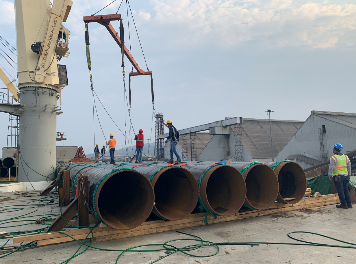
A case study based on a utility tunnel project in Taizhou, China, is used to evaluate steel sheet pile performance. The excavation, located along a riverbank, has a depth of 5–8 m and is situated in a water-rich soft soil area with a high groundwater table (2.5 m below surface). The soil profile consists of silty clay, sandy silt, and soft clay layers.
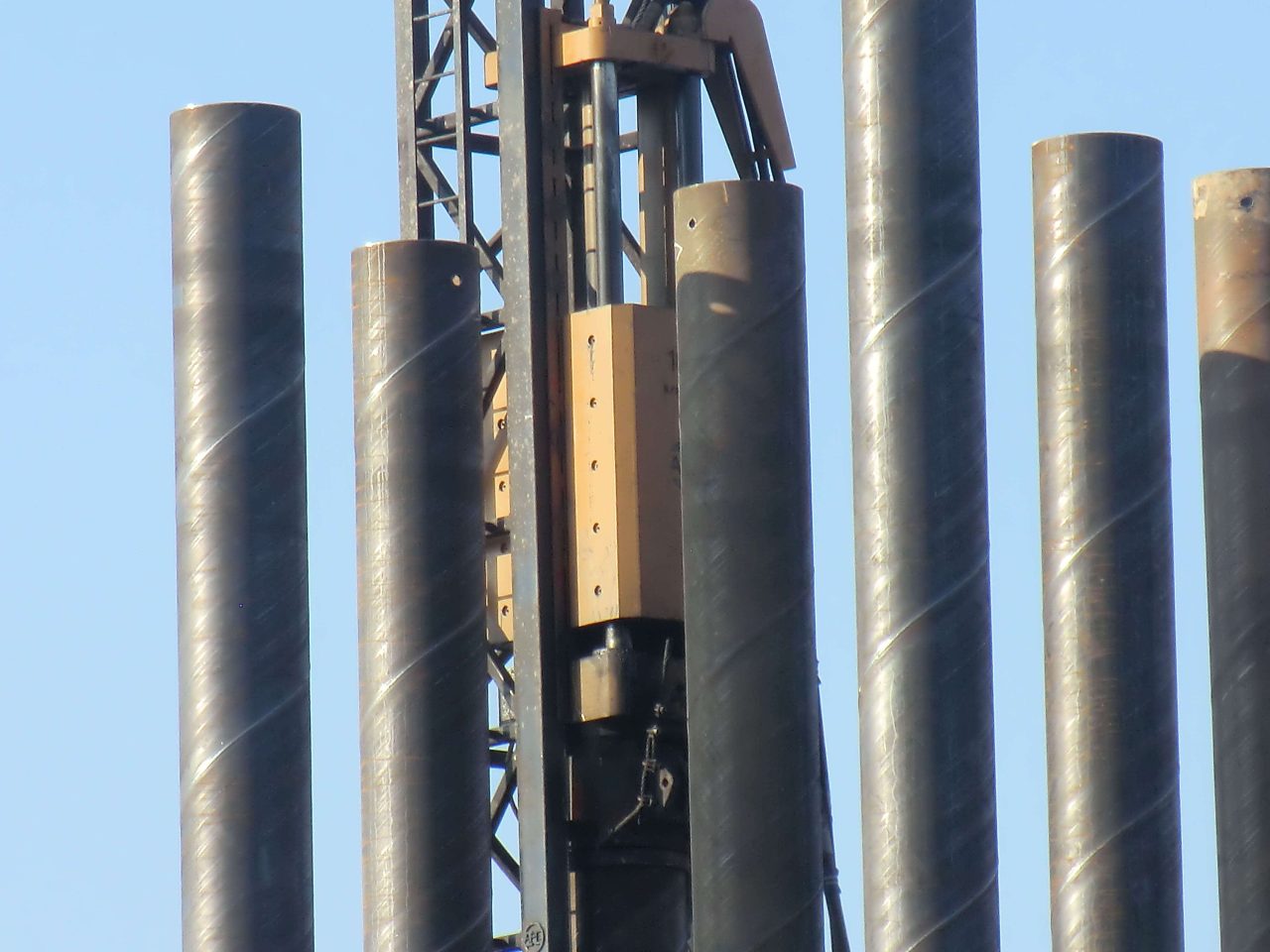
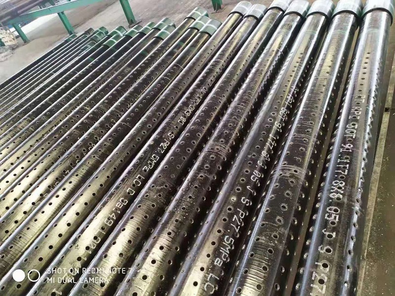
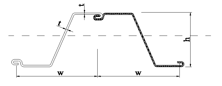
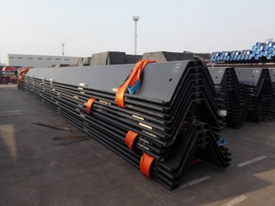
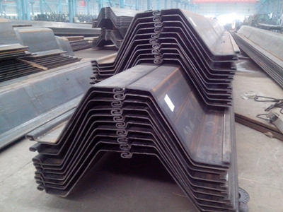
- Pile specifications: IV Larsen steel sheet piles, 400 mm wide, 12 mm thick.
- Reinforcement: H-shaped steel purlins (400 × 400 × 13 × 21 mm) and steel pipe struts.
- Monitoring: Horizontal and vertical displacements at the pile top, axial forces in struts.
3.2. Finite Element Modeling
The excavation was modeled using PLAXIS 2D and 3D finite element software. The Hardening Soil Model with Small Strain Stiffness (HSS) was adopted to simulate soil behavior, accounting for strain-dependent stiffness. Key input parameters included:
- Soil unit weight: 18–20 kN/m³,
- Cohesion: 10–30 kPa,
- Friction angle: 20–30°,
- Young’s modulus: 5–20 MPa.
The steel sheet piles were modeled as linear elastic elements with a modulus of elasticity (\(E\)) of 210 GPa and a moment of inertia (\(I\)) based on the pile cross-section.
3.3. Numerical Analysis
The analysis focused on:
- Lateral displacement: Maximum horizontal displacement (\(u_x\)) at the pile top.
- Bending moment: Maximum bending moment (\(M_{max}\)) along the pile.
- Strut forces: Axial forces in steel struts.
- Settlement: Surface settlement behind the pile wall.
Simulations were conducted for three soil conditions:
- Case A: Silty sand (high stiffness, \(\phi = 30^\circ\)),
- Case B: Soft clay (low stiffness, \(s_u = 20 kPa\)),
- Case C: Mixed layers (silty clay over sandy silt).
4. Results and Discussion
4.1. Lateral Displacement
The maximum lateral displacement (\(u_x\)) varied significantly with soil conditions:
- Case A (Silty sand): \(u_x = 25 \text{ mm}\), within allowable limits (\(u_{all} = 39 \text{ mm}\)).
- Case B (Soft clay): \(u_x = 62.4 \text{ mm}\), exceeding allowable limits, indicating potential instability.
- Case C (Mixed layers): \(u_x = 40 \text{ mm}\), marginally acceptable.
The higher displacement in soft clay is attributed to lower soil stiffness and higher groundwater pressure. The p-y curve analysis confirmed strain-softening behavior in clay, with a peak resistance of \(p_u = 7.5 s_u = 150 \text{ kPa}\).
4.2. Bending Moment
The maximum bending moment (\(M_{max}\)) was calculated as:
- Case A: 180 kNm/m,
- Case B: 223.8 kNm/m,
- Case C: 200 kNm/m.
The higher bending moment in soft clay reflects increased lateral loading due to low passive resistance. The pile section was resized in Case B to meet performance criteria, increasing the section modulus by 20%.
4.3. Strut Forces
Axial forces in struts were:
- Case A: 50–100 kN,
- Case B: 22.51–121.91 kN,
- Case C: 70–110 kN.
The higher forces in Case B indicate greater reliance on internal bracing to maintain stability in soft soil.
4.4. Surface Settlement
Surface settlement behind the pile wall was:
- Case A: 15 mm,
- Case B: 117 mm,
- Case C: 50 mm.
The excessive settlement in Case B highlights the need for additional reinforcement, such as soil stabilization or deeper pile embedment.
4.5. Numerical Comparisons
A parametric study compared cantilever, single-anchored, and double-anchored pile systems:
- Cantilever: \(u_x = 70 \text{ mm}\), \(M_{max} = 250 \text{ kNm/m}\),
- Single-anchored: \(u_x = 40 \text{ mm}\), \(M_{max} = 200 \text{ kNm/m}\),
- Double-anchored: \(u_x = 25 \text{ mm}\), \(M_{max} = 180 \text{ kNm/m}\).
The double-anchored system provided the best performance, reducing displacement by 64% and bending moment by 28% compared to the cantilever system.
5. Scientific Analysis
5.1. Soil-Pile Interaction
The p-y curve analysis revealed that passive pile behavior in soft clay exhibits strain-softening, with a hyperbolic p-δ relationship:
\[ p = \frac{\delta}{a + b \delta} \]
where \(a\) and \(b\): curve-fitting parameters, and \(\delta\): relative soil-pile displacement.
The ultimate soil resistance (\(p_u = 7.5 s_u\)) was validated through field data, showing agreement within 5% of numerical predictions.
5.2. Effect of Excavation Depth
Increasing excavation depth from 5 m to 8 m increased \(u_x\) by 50% and \(M_{max}\) by 30%. The relationship between excavation depth (\(H\)) and displacement is approximated as:
\[ u_x \propto H^{1.5} \]
This nonlinear increase underscores the need for deeper embedment or additional bracing for deeper excavations.
5.3. Influence of Groundwater
Hydrostatic pressure increased lateral loading by 20–30% in water-rich soils. Dewatering reduced \(u_x\) by 15% and \(M_{max}\) by 10%, but required careful management to avoid disturbing the hydrological regime.
6. Design Recommendations
Based on the analysis, the following recommendations are proposed:
- Pile Selection: Use high-strength steel sheet piles (e.g., IV Larsen) with sufficient section modulus to resist bending moments in soft soils.
- Anchoring: Adopt double-anchored systems for excavations deeper than 5 m to minimize displacement and bending moments.
- Soil Stabilization: Implement deep soil-mixing piles or jet grouting in soft clay to enhance soil stiffness and reduce settlement.
- Monitoring: Install inclinometers and geodetic sensors to monitor pile displacement and strut forces in real-time.
- Dewatering: Use controlled dewatering to reduce hydrostatic pressure, with monitoring to prevent excessive groundwater drawdown.