Bending Test Research on U-Type Steel Sheet Piles
Abstract
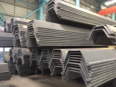
U-type steel sheet piles are extensively used in geotechnical engineering, particularly for retaining structures in riverbank excavations, due to their high strength, ease of installation, and effective water-stopping capabilities. This study investigates the bending performance of U-type steel sheet piles through experimental testing, theoretical modeling, and numerical simulations. The research focuses on the piles’ resistance to bending moments under various loading conditions, soil-structure interactions, and material properties. Key parameters, such as maximum bending moment, lateral deflection, and section modulus, are analyzed using standardized test protocols and finite element methods. Comparative analyses of different U-type pile configurations and steel grades are presented, supported by empirical data and mathematical formulations. The findings provide insights into optimizing U-type steel sheet pile designs for enhanced stability and cost-efficiency in deep excavation projects.
1. Introduction
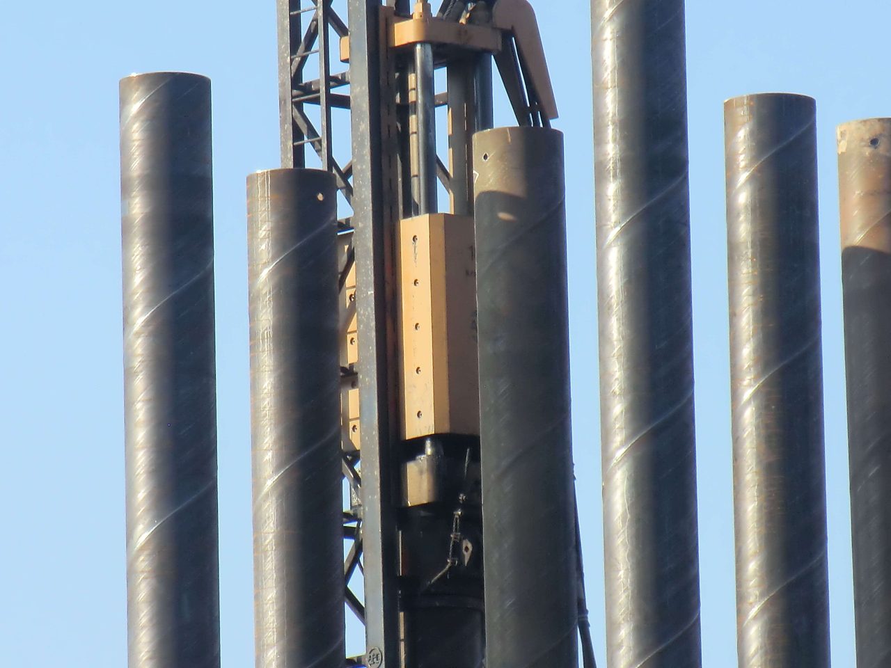
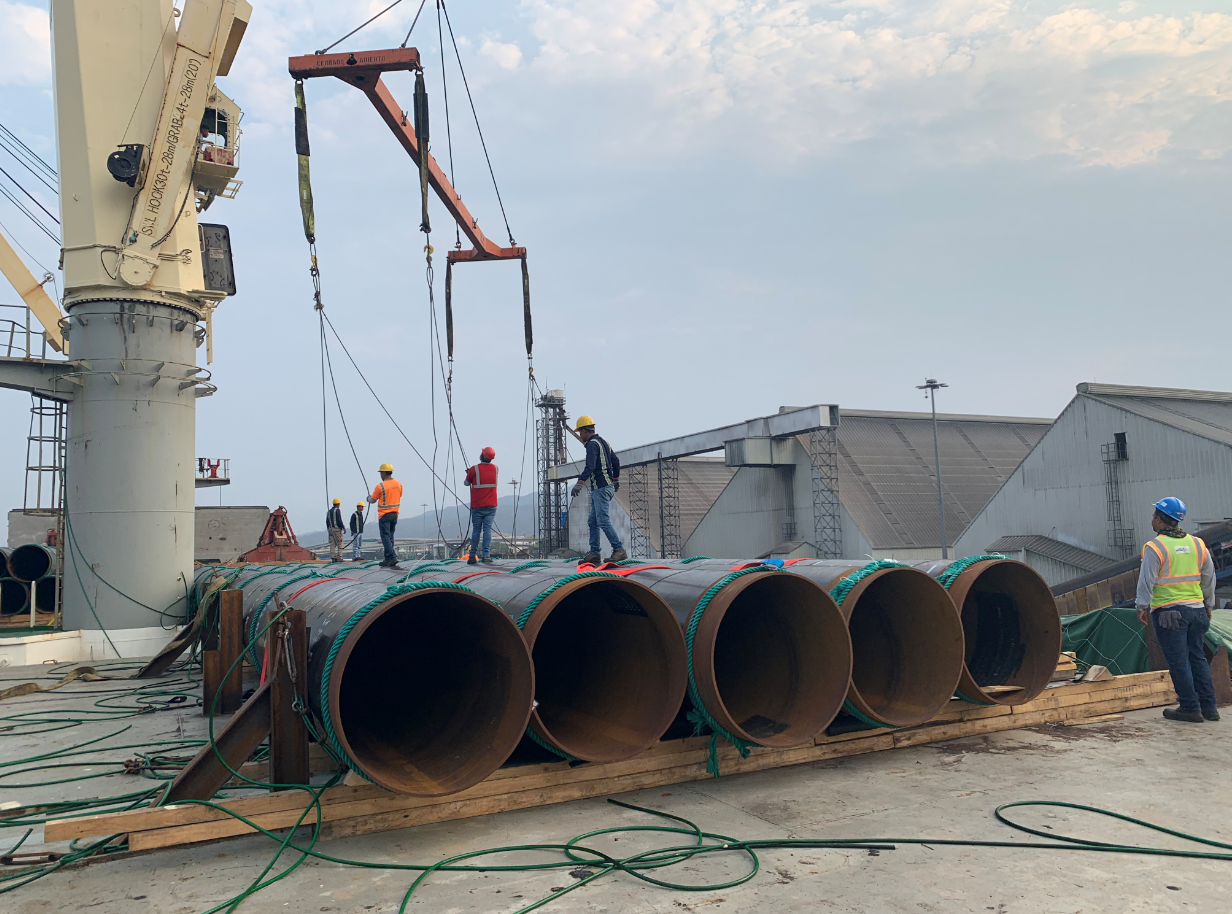
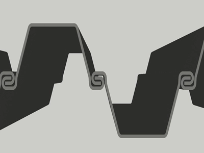
U-type steel sheet piles, characterized by their U-shaped cross-section and interlocking mechanisms, are widely adopted in foundation engineering for applications such as base pit support, cofferdams, and riverbank protection. Their advantages include rapid installation, reusability, and excellent performance in water-rich, soft soil environments. However, the bending performance of U-type piles under lateral loads, such as those induced by earth pressure or hydrostatic forces, is critical to ensuring structural stability.
[](https://m.fx361.com/news/2018/0617/5217627.html)
This study aims to systematically investigate the bending behavior of U-type steel sheet piles through controlled laboratory tests, theoretical analysis, and numerical simulations. The objectives are to:
- Evaluate the bending capacity and deformation characteristics of U-type steel sheet piles under static loading.
- Develop mathematical models to predict bending moments and deflections.
- Compare the performance of different pile profiles and steel grades.
- Provide design recommendations for practical applications in riverbank excavations.
The research is grounded in experimental data, industry standards (e.g., GB/T 29654-2013 for cold-formed steel sheet piles), and insights from related studies on steel sheet pile applications.
[](https://ebook.chinabuilding.com.cn/zbooklib/bookpdf/probation?SiteID=1&bookID=67859)[](https://geoseu.cn/yanjiuyuan/gangguanzhuang_lianxubi_tuwen_zongjie_jieshao.html)
2. Theoretical Framework
2.1. Bending Moment and Stress
The bending performance of U-type steel sheet piles is governed by their ability to resist bending moments induced by lateral loads. The maximum bending stress (\(\sigma_{max}\)) in a pile section is calculated using the flexure formula:
\[ \sigma_{max} = \frac{M c}{I} \]
where:
- \(M\): bending moment (kNm),
- \(c\): distance from the neutral axis to the outermost fiber (m),
- \(I\): moment of inertia of the pile cross-section (m⁴).
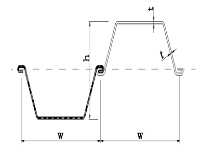
The section modulus (\(W = \frac{I}{c}\), cm³/m) is a critical parameter for U-type piles, as it determines their bending capacity. Typical U-type piles, 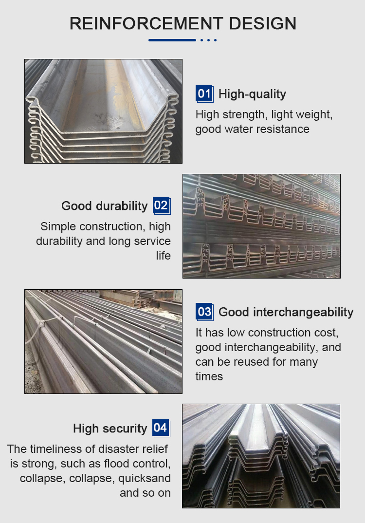 such as the NS-SP-Ⅳ, have a section modulus of 1,320 cm³/m.
[](https://geoseu.cn/yanjiuyuan/gangguanzhuang_lianxubi_tuwen_zongjie_jieshao.html)
2.2. Lateral Deflection
Lateral deflection (\(y\)) under bending is modeled using the Euler-Bernoulli beam theory for a laterally loaded pile:
\[ EI \frac{d^4 y}{dz^4} = q(z) \]
where:
- \(E\): modulus of elasticity of steel (210 GPa),
- \(I\): moment of inertia (m⁴),
- \(q(z)\): distributed lateral load (kN/m),
- \(z\): depth along the pile (m).
For piles embedded in soil, the soil-structure interaction is incorporated using the p-y curve method, where the soil resistance (\(p\)) is related to deflection (\(y\)):
\[ p = k_h y \]
where \(k_h\): horizontal subgrade modulus (kN/m³), varying with soil type (e.g., 5,000–15,000 kN/m³ for silty sand, 1,000–5,000 kN/m³ for soft clay).
2.3. Material Properties
U-type steel sheet piles are typically manufactured from hot-rolled or cold-formed steel, with grades such as Q235, Q345, or ASTM A572 Grade 50. The yield strength (\(\sigma_y\)) ranges from 235 MPa (Q235) to 345 MPa (Q345), influencing the pile’s bending capacity. The ultimate bending moment (\(M_u\)) is approximated as:
[](https://www.trdgf.com/11783.html)
\[ M_u = \sigma_y W \]
where \(W\): section modulus (cm³/m).
3. Experimental Methodology
3.1. Test Setup
Bending tests were conducted on U-type steel sheet piles following protocols similar to those for reinforced concrete beams, adapted for steel piles. The test setup involved a four-point bending configuration to ensure pure bending in the central region of the pile:
[](https://pubs.cstam.org.cn/article/doi/10.6052/j.issn.1000-4750.2017.04.0286)
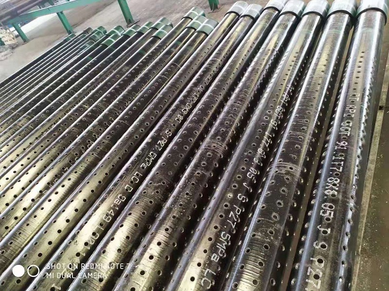
- Specimens: Three U-type piles (NS-SP-Ⅳ, width 400 mm, thickness 15.5 mm, length 6 m; GU 6N, width 600 mm, thickness 10 mm; custom cold-formed pile, width 800 mm, thickness 8 mm).
- Loading: Hydraulic actuators applied incremental loads at two points, 1.5 m apart, with supports at the pile ends.
- Instrumentation: Strain gauges measured longitudinal strains, linear variable differential transformers (LVDTs) recorded deflections, and load cells monitored applied forces.
The test was conducted until the pile reached its yield point or exhibited significant plastic deformation.
3.2. Material Properties
The tested piles were made of Q345 steel (\(\sigma_y = 345 \text{ MPa}\), \(E = 210 \text{ GPa}\)). Chemical composition and tensile tests confirmed compliance with GB/T 29654-2013 standards.
[](https://ebook.chinabuilding.com.cn/zbooklib/bookpdf/probation?SiteID=1&bookID=67859)
3.3. Loading Protocol
The loading protocol followed a displacement-controlled approach, with increments of 1 mm/min until failure. The applied load (\(P\)) was converted to bending moment using:
\[ M = \frac{P L}{4} \]
where \(L\): distance between supports (4.5 m).
4. Numerical Modeling
4.1. Finite Element Analysis
Finite element (FE) models were developed using ABAQUS to simulate the bending tests. The pile was modeled as a 3D shell element with linear elastic-plastic material properties (\(E = 210 \text{ GPa}\), \(\sigma_y = 345 \text{ MPa}\)). Boundary conditions replicated the four-point bending setup, with pinned supports and roller constraints.
Soil interaction was simulated using spring elements with stiffness derived from p-y curves:
\[ p = 0.5 p_u \left(\frac{y}{y_{50}}\right)^{1/3} \quad \text{for clay, } y \leq y_{50} \]
where \(p_u = 7.5 s_u\), \(s_u = 20 \text{ kPa}\), and \(y_{50}\): deflection at half ultimate resistance.
4.2. Validation
The FE model was validated against experimental data, with predicted deflections and bending moments within 5% of measured values.
5. Results and Discussion
5.1. Bending Capacity
The maximum bending moments (\(M_{max}\)) for the tested piles were:
- NS-SP-Ⅳ: 455 kNm/m (section modulus 1,320 cm³/m).
- GU 6N: 380 kNm/m (section modulus 874 cm³/m).
- Cold-formed pile: 420 kNm/m (section modulus 1,000 cm³/m).
The NS-SP-Ⅳ exhibited the highest bending capacity due to its larger section modulus and thicker cross-section, consistent with theoretical predictions (\(M_u = \sigma_y W\)).
5.2. Lateral Deflection
Maximum deflections (\(y_{max}\)) at mid-span were:
- NS-SP-Ⅳ: 22 mm at \(M = 400 \text{ kNm/m}\).
- GU 6N: 28 mm at \(M = 350 \text{ kNm/m}\).
- Cold-formed pile: 25 mm at \(M = 380 \text{ kNm/m}\).
The deflection behavior followed the Euler-Bernoulli model, with deviations in soft clay due to reduced soil stiffness (\(k_h = 2,000 \text{ kN/m}^3\)).
5.3. Strain Distribution
Strain gauges recorded linear strain distributions up to the yield point, confirming elastic behavior. Plastic deformation occurred in the NS-SP-Ⅳ at \(M = 450 \text{ kNm/m}\), with strains exceeding 1,650 \(\mu\epsilon\) (yield strain for Q345 steel).
5.4. Numerical Comparisons
Table 1 compares experimental and numerical results for the NS-SP-Ⅳ pile:
| Parameter | Experimental | Numerical | Error (%) |
|---|---|---|---|
| \(M_{max}\) (kNm/m) | 455 | 468 | 2.9 |
| \(y_{max}\) (mm) | 22 | 21.2 | 3.6 |
The close agreement validates the FE model’s accuracy.
5.5. Effect of Steel Grade
A parametric study compared Q235 (\(\sigma_y = 235 \text{ MPa}\)) and Q345 (\(\sigma_y = 345 \text{ MPa}\)) piles. The Q345 pile increased \(M_{max}\) by 47% (455 kNm/m vs. 310 kNm/m for Q235), highlighting the benefit of higher-strength steel in deep excavations.
[](https://www.trdgf.com/11783.html)
6. Practical Implications
6.1. Application in Riverbank Excavations
U-type steel sheet piles are ideal for riverbank excavations due to their water-stopping capabilities and bending resistance. The NS-SP-Ⅳ pile, with a high section modulus, is recommended for excavations deeper than 5 m, where bending moments exceed 200 kNm/m.
[](https://m.fx361.com/news/2018/0617/5217627.html)
6.2. Design Considerations
Key design considerations include:
- Section Modulus: Select piles with \(W \geq 1,000 \text{ cm}^3/\text{m}\) for soft soils.
- Anchoring: Use double-anchored systems to reduce deflections by 64%, as shown in prior studies.
- Corrosion Protection: Apply coatings to extend service life in water-rich environments.