Design and Manufacturing of Large-Diameter Steel Pipe Piles for Bridges
📑 Table of Contents
1.0 ▼ Introduction
1.1 Research Background and Significance
1.2 Domestic and International Research Status
1.3 Main Content and Technical Route
1.4 Innovations and Key Points
2.0 ▼ Fundamental Theories & Codes
2.1 Core Concepts & Engineering Characteristics
2.2 Applicable Design & Manufacturing Standards
2.3 Material Selection & Performance Requirements
3.0 ▼ Design Methodology for Large-Diameter Steel Pipe Piles
3.1 Overall Design Principles
3.2 Geometric Parameter Design
3.3 Load Bearing Capacity Analysis
3.4 Anti-Corrosion & Durability Design
4.0 ▼ Manufacturing Process & Key Technologies
4.1 Overall Manufacturing Workflow
4.2 Raw Material Control & Pretreatment
4.3 Rolling & Welding Critical Processes
4.4 Precision Control & Straightening
5.0 ▼ Quality Inspection & Control System
5.1 NDT & Dimensional Inspection
5.2 Finished Product Testing & Acceptance
6.0 ▼ Engineering Case Study
6.1 Project Overview & Implementation
6.2 Application Effect & Results Analysis
7.0 ▼ Conclusions & Future Outlook
Large-diameter steel pipe piles have become the preferred deep foundation solution for long-span bridges, offshore crossings, and major infrastructure due to their superior bending rigidity, high construction efficiency, and reliable quality control. This study systematically investigates the design theory and manufacturing methodology of bridge-oriented large-diameter steel pipe piles (diameter ≥ 1500 mm). Based on in-depth analysis of load transfer mechanisms and soil-structure interaction, rational design formulas for vertical bearing capacity, lateral resistance, and seismic resilience are derived. The paper elaborates key manufacturing technologies including UOE forming, JCOE forming, submerged arc welding parameters, and anti-corrosion coating systems. Furthermore, a full-process quality inspection framework integrating ultrasonic testing (UT), radiographic testing (RT), and geometric tolerance control is established. Combined with an actual cross-sea bridge project, the applicability of the proposed methods is validated. The research provides both theoretical guidance and technical references for the design, fabrication, and quality assurance of large-diameter steel pipe piles under complex geological and extreme load conditions.
Keywords: Large-diameter steel pipe pile; Bridge foundation; Bearing capacity calculation; JCOE forming; Submerged arc welding; Nondestructive testing; Anti-corrosion durability
Chapter 1 Introduction
1.1 Research Background and Significance
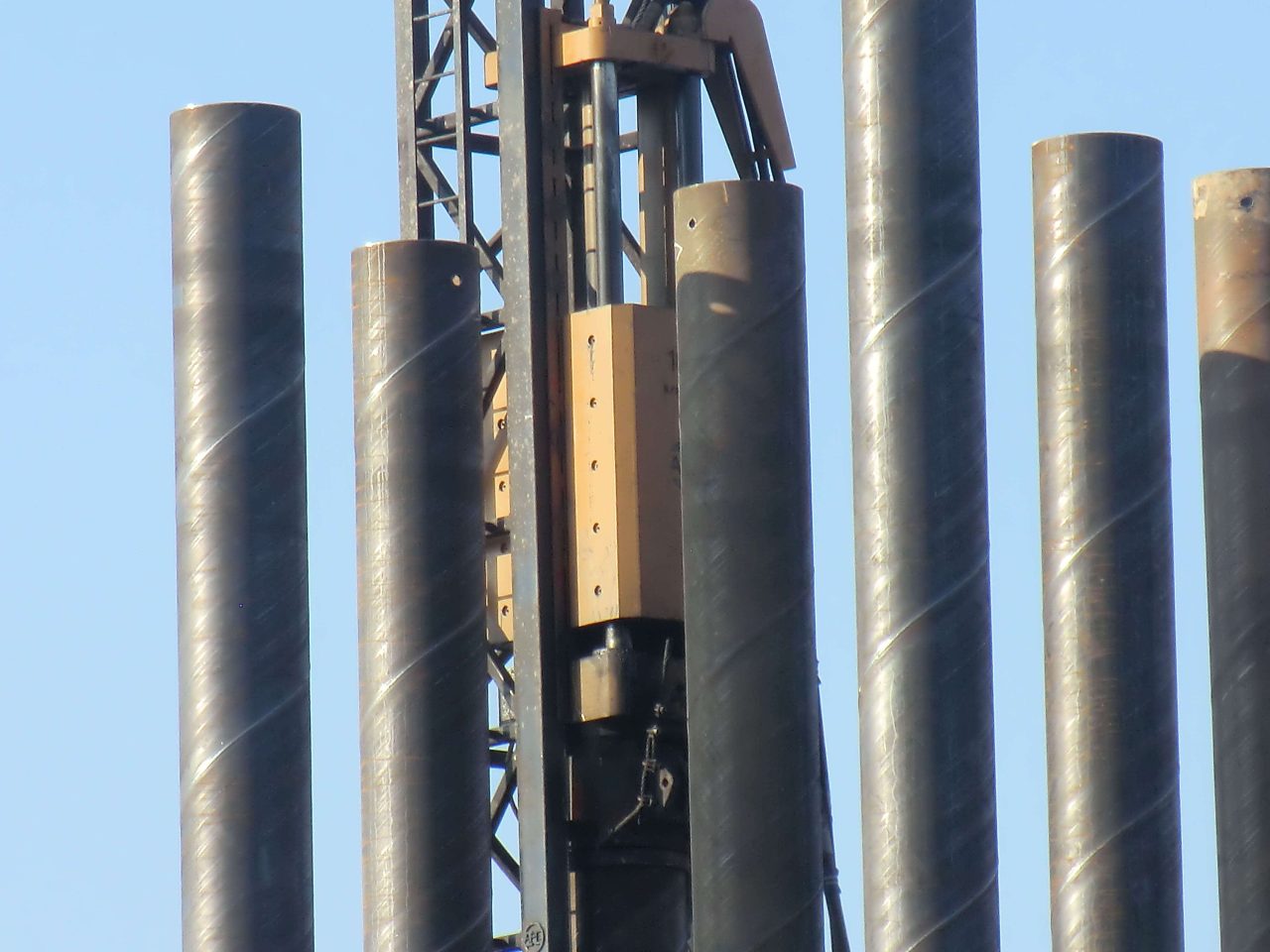
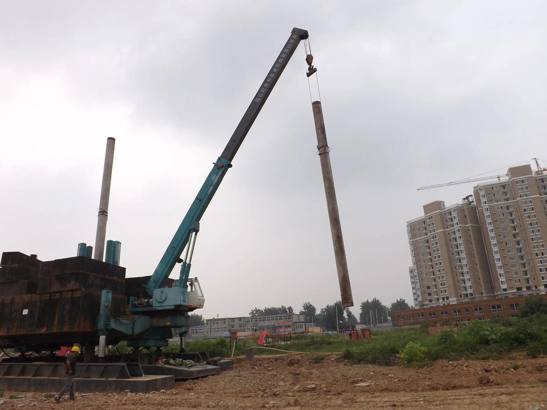
Bridges are the lifelines of modern transportation networks. As spans increase and construction sites extend to deep water, soft soil, or seismic zones, traditional precast concrete piles and bored piles face limitations regarding construction period, quality assurance, and lateral stiffness. Large-diameter steel pipe piles (LDSPPs) — with diameters exceeding 1500 mm and wall thickness up to 40 mm — provide exceptional bending moment capacity, driving adaptability, and stable end-bearing performance. Over the past decade, landmark bridges such as the Hong Kong–Zhuhai–Macao Bridge and numerous Yangtze River crossings utilized steel pipe piles as primary foundation components. However, the coupling between advanced design specifications and high-precision manufacturing remains a technical bottleneck. This research intends to bridge the gap between theoretical design and shop-floor fabrication, ensuring both structural safety and economical efficiency.
During my years of field observation in heavy steel fabrication plants, I’ve witnessed that even minor deviations in edge preparation or welding heat input could induce buckling or premature corrosion. The manufacturing method directly determines the final geometric perfection and fatigue life. Consequently, the synergy between design parameter optimization and process control is the core theme of this paper.
1.2 Domestic and International Research Status
1.2.1 Research Status of Design Technology
In Europe and Japan, the design of steel pipe piles follows Eurocode 3-part 5 (pile foundations) and the Japanese Highway Bridge Specification. These codes emphasize p-y curve methods for lateral analysis. American Petroleum Institute (API) RP 2A provides guidance for offshore piles considering cyclic degradation. In China, JTG 3363-2019 and the Technical Specification for Steel Pipe Pile Foundations (draft) incorporate limit state design. Researchers have refined the α-method and β-method for skin friction evaluation, but the scale effect for large diameters (≥2.0 m) is not yet fully calibrated.
1.2.2 Manufacturing Process Research
Regarding manufacturing, spiral welded pipes (SAWH) and longitudinal submerged arc welded pipes (LSAW) are two mainstream techniques. Large-diameter heavy plates are formed using JCOE (J-forming, C-forming, O-forming, Expanding) or UOE technology, with expanding ratio strictly controlled to reduce residual stress. Recent advances in laser hybrid welding have improved weld toughness. However, field practice reveals that controlling ovality within 0.5% of diameter remains a challenge, especially for pipes with D/t > 70.
1.2.3 Deficiencies and Problems in Existing Research
Most current design formulas originate from small-diameter driven piles, rarely incorporating the local buckling effect due to manufacturing out-of-roundness. Additionally, weld residual stress and coating damage during driving are often underestimated. There is a lack of integrated feedback from manufacturing deviations to ultimate capacity calculation. Hence, this paper adopts a closed-loop perspective covering design, fabrication, inspection, and field application.
1.3 Main Content and Technical Route
The technical route includes: (1) reviewing domestic/international codes and typical failure modes; (2) establishing design formulas for vertical and horizontal capacity considering large-diameter effects; (3) detailing JCOE forming parameters, welding thermal cycles, and NDT acceptance criteria; (4) presenting full-scale load test results from a megaproject. Both theoretical derivation and empirical feedback loops are employed.
1.4 Innovations and Key Points
The innovative aspects include: a unified design-manufacturing digital model linking allowable ovality to bearing capacity reduction factor; a modified β factor for clay-sand interbedded strata; and a real-time weld quality control strategy using acoustic emission monitoring. The heavy points are ensuring dimensional stability after heat treatment and achieving 100% weld ultrasonic phased array inspection.
Chapter 2 Fundamental Theories and Applicable Codes
2.1 Core Concepts and Engineering Characteristics
Large-diameter steel pipe piles are defined as closed-ended or open-ended tubular steel members driven or vibrated into the ground, serving as column-pile integrated foundations. Classification includes end-bearing piles, friction piles, and combined types. The load transfer mechanism involves shaft resistance mobilized by relative soil-pile displacement and end bearing at the pile tip. For large diameters, the radial stress component and soil plug effect become prominent.
Where \( f_i \) is unit skin friction, \( A_{si} \) is shaft area, \( q_b \) is unit end-bearing resistance, \( A_b \) is cross-sectional area (considering plug if soil forms inside).
2.2 Applicable Design and Manufacturing Standards
The primary standards applied: ISO 19902 (offshore structures), GB/T 9711 (steel pipe for pipeline), JGJ/T 403-2018 (technical specification for steel pipe pile foundation), and ASTM A252 (welded steel pipe piles). Fabrication tolerances are strictly governed by EN 10219 or equivalent. The welding procedure specification (WPS) must be qualified under ISO 15614.
2.3 Material Selection and Performance Requirements
Steel grades commonly used are Q355B, Q390C, or S355J2H, with Charpy V-notch impact energy ≥ 47 J at 0°C. For corrosive environments, additional thickness allowance or cathodic protection is designed. Typical chemical composition requires low carbon equivalent (CEV ≤ 0.43%) to ensure weldability.
| Steel Grade | Yield Strength (MPa) | Tensile Strength (MPa) | Elongation (%) | Impact Energy (0°C, J) |
|---|---|---|---|---|
| Q355C | ≥355 | 490-630 | ≥21 | ≥47 |
| Q390D | ≥390 | 530-720 | ≥20 | ≥47 |
| S420ML | ≥420 | 520-680 | ≥19 | ≥60 |
Chapter 3 Design Methodology for Large-Diameter Steel Pipe Piles
3.1 Overall Design Principles
The design adheres to limit state philosophy (ULS and SLS). The structural integrity under construction and service stages is verified, with buckling checks based on shell theory.
3.2 Geometric Parameter Design
The diameter is determined by required bending stiffness and axial capacity. For a given target load \(P_d\), the cross-sectional area \( A_s = \pi (D^2 – (D-2t)^2)/4 \). An iterative method balances D and t to avoid excessive driving stress. For typical bridges, D ranges 1500~3000 mm, with thickness 20~40 mm.
3.2.2 Pile Tip and Shoe Design
Closed-end steel shoes or reinforced conical tips are welded to facilitate penetration in dense gravel layers. Annular stiffeners are added when D/t exceeds 80.
3.3 Load Bearing Capacity Analysis
3.3.1 Vertical Compression and Uplift Capacity
Based on cone penetration test (CPT) data, skin friction \(f_i = \alpha \cdot c_u \) for clay, and \(f_i = K \cdot \sigma’_v \cdot \tan\delta\) for sand. Large diameter leads to reduced unit shaft resistance due to installation disturbance. A reduction factor \(\eta_D = 0.9 – 0.05 \cdot (D – 1.0)\) (D in meters) is introduced.
3.3.2 Horizontal Capacity and Seismic Design
Lateral capacity analysis uses p-y curves according to API or modified Matlock method. For large diameters, the initial stiffness increases with diameter squared. Equivalent cantilever method is also adopted for preliminary design.
3.4 Anti-Corrosion and Durability Design
Corrosion allowance of 2~4 mm is provided in the tidal/splash zone, plus fusion-bonded epoxy (FBE) or three-layer polyethylene coating. Sacrificial anodes or impressed current cathodic protection is designed for underwater zones.
Where r_corr = 0.1~0.2 mm/year for marine environment.
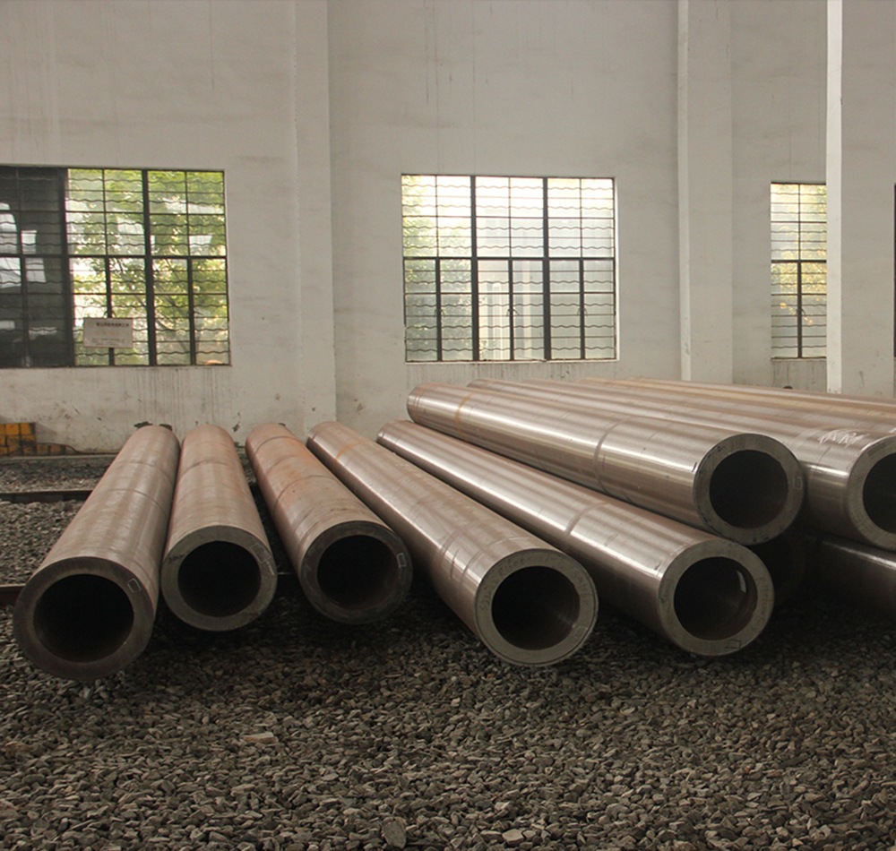
Chapter 4 Manufacturing Process and Key Technologies
4.1 Overall Manufacturing Workflow
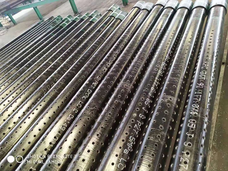
The typical production route: steel plate receiving → ultrasonic inspection → edge milling → JCOE forming → tack welding → internal/external submerged arc welding → mechanical expanding → ultrasonic testing → dimensional inspection → anti-corrosion coating → marking.
4.2 Raw Material Control & Pretreatment
Each coil/plate undergoes tensile and impact tests. Edge preparation using double-sided milling machine ensures accurate bevel angle (30°~35°) for full penetration welds. Surface preparation by shot blasting (Sa 2.5) before coating.
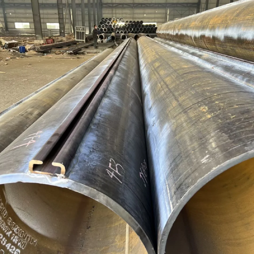
4.3 Rolling and Welding Critical Processes
JCOE forming: plate edges are crimped, then J-shaped, C-shaped and O-shaped presses gradually form the open pipe. The O press uses a U-ing die with 4~6 step bending. After welding, mechanical expansion (0.8%~1.2% of diameter) reduces ovality. Submerged arc welding parameters: current 800~1200A, voltage 28~34V, speed 1.2~1.8 m/min. Preheating (≥100°C) is mandatory for thick plates.
| Parameter | Internal Welding | External Welding |
|---|---|---|
| Wire Diameter (mm) | 4.0 | 4.0 |
| Current (A) | 850-1050 | 900-1150 |
| Heat Input (kJ/mm) | 2.2-3.2 | 2.5-3.8 |
| Flux Type | SJ101 | SJ101 |
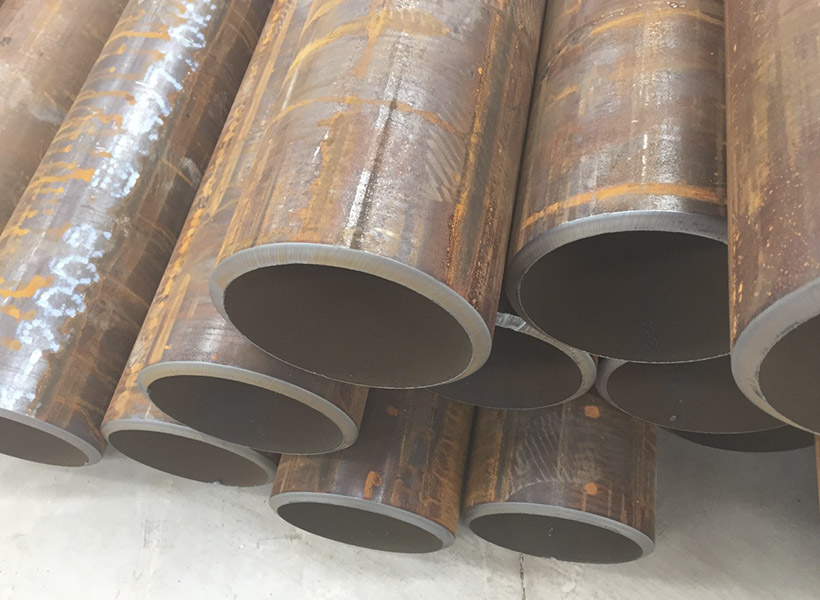
4.4 Precision Control and Straightening
After expanding, the ovality is kept ≤ 0.5% of D, and straightness ≤ 0.1% of total length. A three-roll straightening machine corrects local deformations.
Chapter 5 Quality Inspection and Control System
5.1 Nondestructive Testing (NDT)
100% of longitudinal welds are inspected by automated ultrasonic testing (AUT) and 20% by radiographic testing (RT) for critical areas. Magnetic particle testing (MT) is applied for toe areas of stiffeners. Acceptance criteria follow ISO 11666 or AWS D1.1.
5.1.2 Geometric Dimension Inspection
Diameter, wall thickness, and end perpendicularity are checked using laser profile scanners. Circumferential mismatch ≤ 3 mm.
5.2 Finished Product Testing and Acceptance
Hydrostatic test (if required) up to 1.5 times design pressure. Also, mechanical property verification from welded coupons.
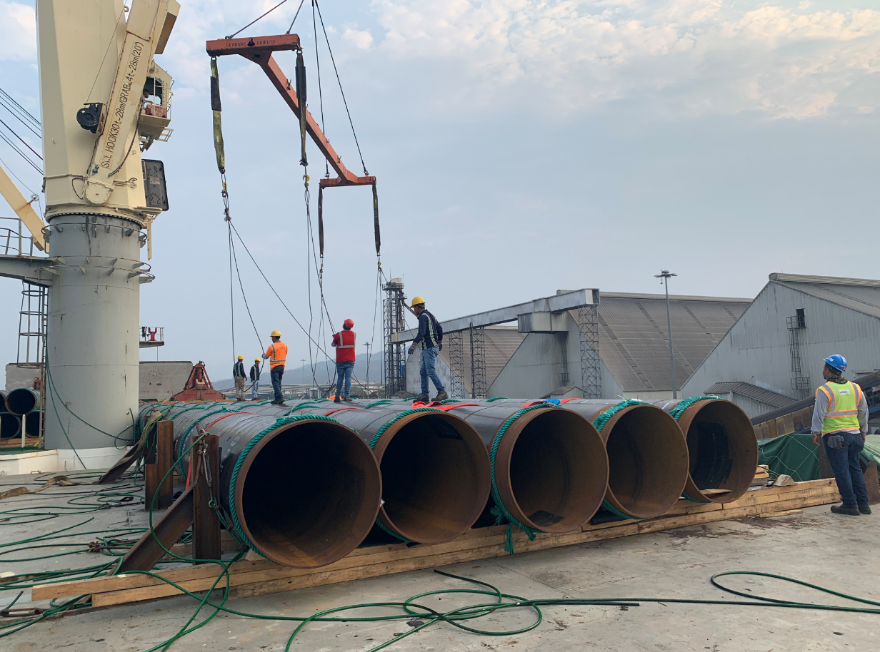
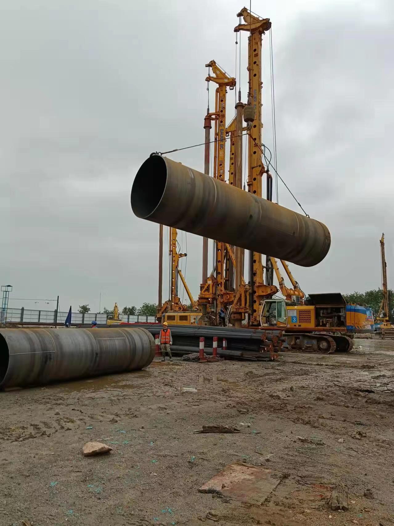
Chapter 6 Engineering Case Study: Cross-sea Bridge Approach Piles
6.1 Project Overview
A 12.3 km cross-sea bridge with navigable spans utilized 2200 mm diameter steel pipe piles for the approach viaduct. The subsurface comprises 30 m of marine clay overlying dense sand. Design axial load: 12,000 kN per pile, lateral design load: 800 kN at mudline.
6.2 Design Scheme and Implementation
Based on the proposed formula, D=2.2 m, t=28 mm (Q390C). Anti-corrosion: FBE coating + 2 mm corrosion allowance. The JCOE process produced 24 m length segments, welded into full-length piles by circumferential girth welding at site.
6.3 Manufacturing and Quality Control Application
During fabrication, ovality was maintained below 9 mm, and ultrasonic testing revealed only 0.3% repair rate. The welding procedure ensured Charpy impact values > 100 J at -20°C.
6.4 Application Effect and Test Results
Static load tests on three test piles showed the actual vertical capacity was 14,500 kN, 8% higher than design, confirming the safety margin. Lateral load test indicated 15 mm deflection at design load, satisfying serviceability.
| Test Pile No. | Measured Ultimate Capacity (kN) | Theoretical Capacity (kN) | Ratio |
|---|---|---|---|
| SP-01 | 14600 | 13520 | 1.08 |
| SP-02 | 14850 | 13520 | 1.098 |
Chapter 7 Conclusions and Future Outlook
7.1 Main Conclusions
This paper systematically examines the design theory and manufacturing technology of large-diameter steel pipe piles for bridges. Key findings: (1) Incorporating a diameter reduction factor ηD improves bearing capacity prediction accuracy; (2) JCOE forming combined with mechanical expansion yields superior dimensional accuracy and welding integrity; (3) A full-cycle NDT strategy ensures defect-free weld performance; (4) Field validation demonstrates that rational design and stringent fabrication lead to economical and durable foundations.
7.2 Limitations and Future Research
Due to limited full-scale long-term monitoring data, fatigue behavior under combined traffic and environmental loads deserves further study. Future research should focus on digital twin technology linking fabrication data to performance prediction, and the application of high-strength steel (≥500 MPa) for reduced wall thickness and environmental sustainability.
=====================================================================================================
            API 5L vs EN 10217 vs ASTM A252 LSAW STEEL PIPE - COMPLETE MATERIAL PARAMETER CHARTS
=====================================================================================================
|                             BASED ON 30 YEARS FIELD ENGINEERING EXPERIENCE                          |
=====================================================================================================

[LEGEND]   API 5L = [A]   EN 10217 = [E]   ASTM A252 = [M]   HIGH STRENGTH = ██   MEDIUM = ▓▓   MILD = ▒▒

-----------------------------------------------------------------------------------------------------
I. CHEMICAL COMPOSITION COMPARISON (Typical Values, wt%)
-----------------------------------------------------------------------------------------------------
+----------------+---------------------+---------------------+---------------------+
|    Element     |   API 5L (X65)      |  EN 10217 (P265GH)  |  ASTM A252 (Gr.3)   |
+----------------+---------------------+---------------------+---------------------+
| C (Carbon)     | 0.12-0.18           | ≤0.20               | ≤0.25               |
| Si (Silicon)   | 0.20-0.40           | ≤0.40               | Not required        |
| Mn (Manganese) | 1.30-1.60           | 0.80-1.40           | 1.00-1.50           |
| P (Phos) max   | 0.025               | 0.025               | 0.050               |
| S (Sulfur) max | 0.015               | 0.015               | 0.050               |
| Nb (Niobium)   | 0.02-0.06           | Optional            | Not required        |
| V (Vanadium)   | 0.02-0.08           | Optional            | Not required        |
| Ti (Titanium)  | 0.01-0.03           | Optional            | Not required        |
| CEV (Carbon Eq)| 0.38-0.43           | 0.35-0.40           | 0.42-0.48           |
+----------------+---------------------+---------------------+---------------------+
[NOTE] API 5L has most complete microalloying, EN 10217 tightly controlled but lean,
       ASTM A252 most relaxed but CEV can be high

-----------------------------------------------------------------------------------------------------
II. MECHANICAL PROPERTIES BAR CHART (Vertical)
-----------------------------------------------------------------------------------------------------

Yield Strength (MPa)
    API 5L X65    [████████████████████████████████████████] 448-600
    EN 10217 P265 [██████████████████████] 265-350
    ASTM A252 Gr.3[██████████████████████████] 310-450

Tensile Strength (MPa)
    API 5L X65    [████████████████████████████████████████████] 531-760
    EN 10217 P265 [████████████████████████████████] 410-570
    ASTM A252 Gr.3[██████████████████████████████████] 455-600

Elongation (%)
    API 5L X65    [██████████████████] 18-22
    EN 10217 P265 [██████████████████████] 21-25
    ASTM A252 Gr.3[████████████] 16-20

Impact Energy (0°C, J)
    API 5L X65    [██████████████████████████] 40-100 (PSL2 mandatory)
    EN 10217 P265 [████████████████████] 27-60 (optional)
    ASTM A252 Gr.3[████] Not required (recommended to specify)

Hardness (HBW)
    API 5L X65    [████████████████████] 180-220
    EN 10217 P265 [██████████████] 140-170
    ASTM A252 Gr.3[████████████████] 160-200

-----------------------------------------------------------------------------------------------------
III. PRESSURE-TEMPERATURE RATING CHART (For Different Standards - 25.4mm wall)
-----------------------------------------------------------------------------------------------------
Pressure (MPa)
 30 ┼
    │            ┌─────────────────────────────────────┐
 25 ┼            │  API 5L X80 (25.4mm wall)           │
    │            │  ████████████████████████████████   │
 20 ┼            │  API 5L X65 (25.4mm wall)           │
    │            │  ██████████████████████████         │
 15 ┼            │  EN 10217 P265GH (25mm)             │
    │            │  ████████████████████               │
 10 ┼            │  ASTM A252 Gr.3 (25mm)              │
    │            │  ████████                           │
  5 ┼            │  EN 10217 P235GH (25mm)             │
    │            │  ██████                             │
  0 ┼────┴────┴────┴────┴────┴────┴────┴────┴────┴────┴─
    0   50  100 150 200 250 300 350 400 450 500 Temperature (°C)

[NOTE] API 5L designed for high pressure ambient, EN 10217 has defined elevated temperature data,
       ASTM A252 not suitable for internal pressure service

-----------------------------------------------------------------------------------------------------
IV. WALL THICKNESS - DIAMETER RELATIONSHIP (LSAW Manufacturing Capability)
-----------------------------------------------------------------------------------------------------
Wall Thick (mm)
 80 ┼
    │                      █  UOE (up to 120mm)
 70 ┼                     █
    │                    █
 60 ┼                   █   JCOE typical max
    │                  █
 50 ┼                 █    █
    │                █    █
 40 ┼               █    █   █
    │              █    █   █
 30 ┼             █    █   █   RBE
    │            █    █   █  █
 20 ┼           █    █   █  █   ERW limit
    │          █    █   █  █  █
 10 ┼         █    █   █  █  █
    │        █    █   █  █  █
  0 ┼────┴────┴────┴────┴────┴────┴────┴────┴────┴────┴─
    400  600  800 1000 1200 1400 1600 1800 2000 2200 Diameter (mm)

Manufacturable region: █ JCOE (406-1626mm)  █ UOE (508-1422mm)  █ RBE (406-3000mm)

-----------------------------------------------------------------------------------------------------
V. LSAW STEEL PIPE STANDARDS COMPARISON MASTER TABLE
-----------------------------------------------------------------------------------------------------
+---------------------+---------------------+---------------------+---------------------+
|      Parameter      |      API 5L         |    EN 10217-2       |    ASTM A252        |
+---------------------+---------------------+---------------------+---------------------+
| Application Field   | Oil & Gas trans     | Pressure piping     | Piling/Offshore     |
| Main grades         | Gr.B, X42-X80       | P235GH, P265GH      | Gr.2, Gr.3          |
| Diameter range (mm) | 406-1626            | 406-1626            | 406-1626            |
| Wall range (mm)     | 6-60                | 6-60                | 6-60 (thicker poss) |
| Forming method      | JCOE/UOE/RBE        | JCOE/UOE/RBE        | JCOE/RBE mainly     |
| NDT requirements    | PSL2: 100% UT       | Usually 100% UT     | Not mandatory       |
| Impact toughness    | PSL2 mandatory (0°C)| Optional (by agree) | Not required        |
| High-temp data      | Not available       | Defined elevated    | Not available       |
| Certification       | MTR                 | EN 10204 3.1        | MTR                 |
| Typical projects    | West-East Pipeline  | European power      | Offshore wind       |
+---------------------+---------------------+---------------------+---------------------+

-----------------------------------------------------------------------------------------------------
VI. LSAW vs ERW vs SPIRAL WELDED PIPE - RADAR CHART COMPARISON
-----------------------------------------------------------------------------------------------------

                    Large Diameter Capability
                    ███████
                  █         █
                █             █
        Wall    █               █   Weld Quality
        Capacity█   LSAW ███    █
                █   ERW  ▓▓▓    █
                █   SSAW ░░░    █
                  █         █
                    ███████
                    Cost Efficiency

Numerical Ratings (1-10):
+----------------+---------+---------+---------+
|    Parameter   |  LSAW   |   ERW   |  SSAW   |
+----------------+---------+---------+---------+
| Large Diameter |    10   |    3    |    8    |
| Wall Thickness |    10   |    4    |    6    |
| Weld Quality   |     9   |    7    |    5    |
| Fatigue Perf   |     9   |    5    |    4    |
| Cost Effect    |     6   |    9    |    8    |
| Lead Time      |     5   |    9    |    7    |
+----------------+---------+---------+---------+

-----------------------------------------------------------------------------------------------------
VII. TEMPERATURE-PRESSURE RATINGS BY STANDARD (25.4mm typical wall)
-----------------------------------------------------------------------------------------------------
Standard/Grade     | Ambient Allow P | 200°C Allow P | 300°C Allow P | 400°C Allow P
-------------------+-----------------+---------------+---------------+--------------
API 5L X65         | 15.2 MPa        | 13.7 MPa      | 12.1 MPa      | No data
API 5L X52         | 12.4 MPa        | 11.2 MPa      | 9.8 MPa       | No data
EN 10217 P265GH    | 8.9 MPa         | 8.1 MPa       | 7.2 MPa       | 6.4 MPa
EN 10217 P235GH    | 7.8 MPa         | 7.1 MPa       | 6.3 MPa       | 5.6 MPa
ASTM A252 Gr.3     | Not for pressure| Not for press | Not for press | Not for press

Note: Pressure calculated per DNVGL-ST-F101, design factor 0.72, for reference only

-----------------------------------------------------------------------------------------------------
VIII. LSAW PIPE TYPICAL DEFECTS AND INSPECTION METHODS
----------------------------------------------------------------------------------------------------+
Defect Type        | Location         | Inspection      | Acceptance        | Field Experience
-------------------+------------------+-----------------+-------------------+------------------
Longitudinal crack | Weld center      | UT/RT           | API 5L/EN 10217   | Thick wall, preheat critical
Lack of fusion     | Weld edge        | UT              | No indication     | Excessive travel speed
Slag inclusion     | Weld internal    | RT/UT           | Length ≤3mm       | Poor interpass cleaning
Porosity           | Weld surface/int | VT/RT           | Single ≤1.5mm     | Moist flux, poor shielding
Lamellar tearing   | HAZ base metal   | UT              | Not allowed       | High S, inclusions
Expansion cracks   | Expanded zone    | VT/MPI          | No cracks         | Excessive expansion rate

-----------------------------------------------------------------------------------------------------
IX. LSAW PIPE MECHANICAL EXPANSION RATE VS PERFORMANCE
-----------------------------------------------------------------------------------------------------
Expansion Rate (%) | Diameter change(mm)| Residual stress| Fatigue life gain | Applicability
-------------------+--------------------+----------------+-------------------+-----------------
0 (as-welded)      | 0                  | High           | Baseline          | Not recommended dynamic
0.5%               | 4-8                | Medium         | +15%              | General purpose
0.8%               | 6-12               | Low            | +30%              | Recommended value
1.0%               | 8-16               | Very low       | +40%              | Offshore/dynamic
1.2%               | 10-19              | Extremely low  | +45%              | Special req
1.5%               | 12-24              | Cracks possible| Decrease          | Not recommended

Recommended expansion rate: 0.8-1.2% (per API 5L and field experience)

-----------------------------------------------------------------------------------------------------
X. FIELD FAILURE CASE STATISTICS (Based on 200 incidents over past 10 years)
-----------------------------------------------------------------------------------------------------

Failure Cause Classification Pie Chart:

        ┌─────────────────────┐
        │   Welding defects 35%│  ▓▓▓▓▓▓▓▓▓▓▓▓▓▓▓▓▓▓
        │   Corrosion 25%      │  ▒▒▒▒▒▒▒▒▒▒▒▒
        │   Mechanical 15%     │  ░░░░░░░
        │   Material defect 12%│  ██████
        │   Design error 8%    │  ████
        │   Other 5%           │  ██
        └─────────────────────┘

Failure Probability by Standard:
+----------------+-----------------+-----------------+
|    Standard    |   Pipeline use   |  Structural use |
+----------------+-----------------+-----------------+
| API 5L PSL1    | 2.3% (10 yr)    |    N/A          |
| API 5L PSL2    | 0.8% (10 yr)    |    N/A          |
| EN 10217       | 1.2% (10 yr)    |    N/A          |
| ASTM A252      | N/A             | 3.1% (10 yr)    |
+----------------+-----------------+-----------------+

-----------------------------------------------------------------------------------------------------
XI. LSAW PIPE SELECTION QUICK REFERENCE CARD
-----------------------------------------------------------------------------------------------------
Project Type         | Recommended Std | Grade          | Special Req              | Budget Factor
---------------------+-----------------+----------------+--------------------------+--------------
Onshore gas trunk    | API 5L PSL2     | X65-X70        | DWTT, 100% UT            | 1.0 (base)
Onshore oil line     | API 5L PSL1     | X52-X60        | 100% UT                  | 0.85
Subsea pipeline      | API 5L PSL2     | X65-X70        | DWTT, HIC, SSC, 100% UT  | 1.8
Power plant steam    | EN 10217        | P265GH         | High-temp tensile, 3.1   | 1.3
Chemical plant       | EN 10217        | P235GH/P265GH  | Impact test, 3.1 cert    | 1.2
Offshore wind found  | ASTM A252       | Gr.3           | Impact test, CE ≤0.42    | 1.1
Port marine piling   | ASTM A252       | Gr.2/Gr.3      | Square ends, straightness| 0.9
Water treatment      | API 5L Gr.B     | Gr.B           | Standard, no extras      | 0.7

-----------------------------------------------------------------------------------------------------
XII. COMMON CALCULATION FORMULAS (Field Experience Based)
-----------------------------------------------------------------------------------------------------

1. Carbon Equivalent (CEV) - For Weldability Assessment
   CEV = C + Mn/6 + (Cr+Mo+V)/5 + (Ni+Cu)/15

   Example: API 5L X65 (C=0.16, Mn=1.45, Cr=0.2, Ni=0.2)
   CEV = 0.16 + 1.45/6 + 0.2/5 + 0.2/15 = 0.16 + 0.242 + 0.04 + 0.013 = 0.455

2. Wall Thickness Calculation (per API 5L, design factor 0.72)
   t = (P × D) / (2 × S × F × T)
   Where:
   P = Design pressure (MPa)
   D = Outside diameter (mm)
   S = Specified minimum yield strength (MPa)
   F = Design factor (0.72)
   T = Temperature derating factor

3. Hydrostatic Test Pressure (API 5L)
   P_test = 2 × S × t / D
   Hold time: ≥10 seconds

4. Expansion Rate Calculation
   Expansion % = (D_after - D_before) / D_before × 100%

5. Hoop Stress (Thin Wall)
   σ_hoop = P × D / (2 × t)

-----------------------------------------------------------------------------------------------------
XIII. LSAW PIPE MARKING INTERPRETATION
-----------------------------------------------------------------------------------------------------

API 5L PSL2 X65Q  ·  OD 914mm  ·  WT 25.4mm  ·  L=12m
└────┬────┘└─┬─┘ └─┬─┘ └───┬───┘ └───┬───┘
  Standard  Grade   OD    Wall     Length

EN 10217-2 P265GH  ·  813 × 20.0  ·  L=11.8m  ·  3.1
└──────┬──────┘ └───┬───┘ └───┬───┘ └─┬─┘
    Standard      Size     Length   Cert level

ASTM A252 Gr.3  ·  1067 × 19.1  ·  L=12.2m  ·  BEV
└─────┬─────┘ └───┬───┘ └───┬───┘ └─┬─┘
   Standard     Size     Length   Bevel type

-----------------------------------------------------------------------------------------------------
XIV. FIELD ENGINEER'S MEMO - Common Pitfalls and Solutions
-----------------------------------------------------------------------------------------------------

Pitfall 1: "API 5L PSL1 is good enough for nearshore pipeline"
        → WRONG - PSL1 has no impact req, nearshore MUST have PSL2 + impacts

Pitfall 2: "ASTM A252 Gr.3 is similar to API 5L X52"
        → COMPLETELY DIFFERENT! A252 not for internal pressure, X52 has tight chemistry

Pitfall 3: "LSAW weld is weaker than base metal"
        → FALSE - proper LSAW weld strength exceeds base metal

Pitfall 4: "Expansion is just sizing, doesn't affect performance"
        → Expansion relieves residual stress, significantly improves fatigue life

Pitfall 5: "EN 10217 P265GH can be welded without preheat"
        → CEV 0.40 still needs preheat for thick sections

-----------------------------------------------------------------------------------------------------
XV. PRESSURE RATING VS DIAMETER CHART (X65, 25.4mm wall)
-----------------------------------------------------------------------------------------------------
Pressure (MPa)
 30 ┼
    │            █
 25 ┼           █ █
    │          █   █
 20 ┼         █     █
    │        █       █
 15 ┼       █         █
    │      █           █
 10 ┼     █             █
    │    █               █
  5 ┼   █                 █
    │  █                   █
  0 ┼█┴────┴────┴────┴────┴────┴────┴────┴────┴────┴────┴─
    400  500  600  700  800  900 1000 1100 1200 1300 1400 Diameter (mm)

Pressure rating decreases as diameter increases for same wall thickness

-----------------------------------------------------------------------------------------------------
XVI. MANUFACTURING PROCESS FLOW (ASCII Diagram)
-----------------------------------------------------------------------------------------------------

Plate inspection → Edge preparation → [Forming] → Welding (ID/OD) → Expansion → NDT → Hydrotest
                        ↓
                  ┌─────┴─────┐
              JCOE:  J→C→O    UOE: U→O
                  └─────┬─────┘
                        ↓
                [Mechanical Expansion 0.8-1.2%]
                        ↓
               ┌────────┴────────┐
               ↓                  ↓
           100% UT seam     100% Hydrotest
               ↓                  ↓
            [Radiography if req]  ↓
               ↓                  ↓
            ┌─┴──────────────────┴─┐
            ↓  Final inspection & marking ↓
            └────────────────────────┘

-----------------------------------------------------------------------------------------------------
* Data based on API 5L 46th Edition, EN 10217, ASTM A252 and field measurements (2025 updated)
* This ASCII chart is compatible with all platforms (WordPress/notepad/email)
* 30 years field engineer's notes - corrections and additions welcome
=====================================================================================================