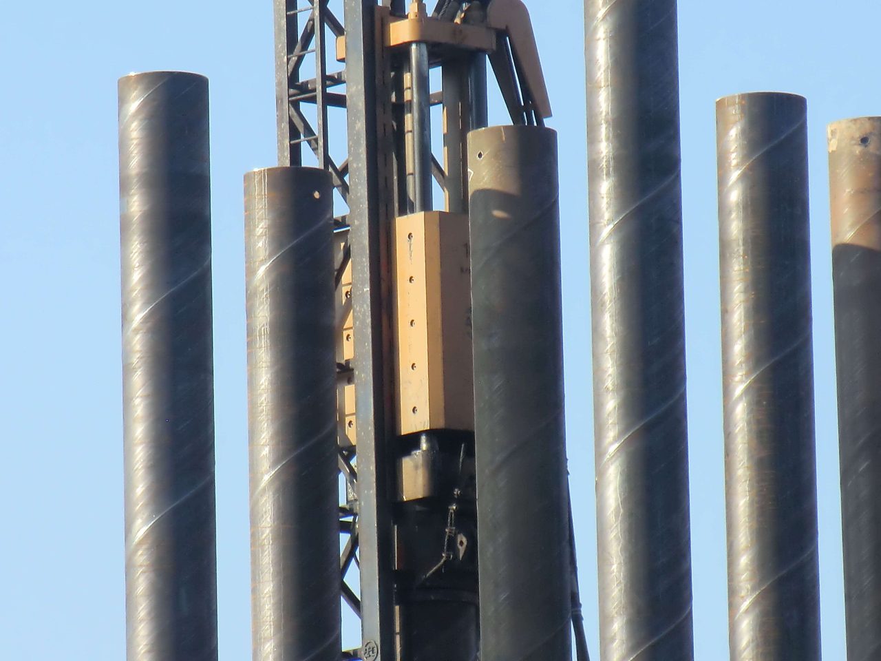
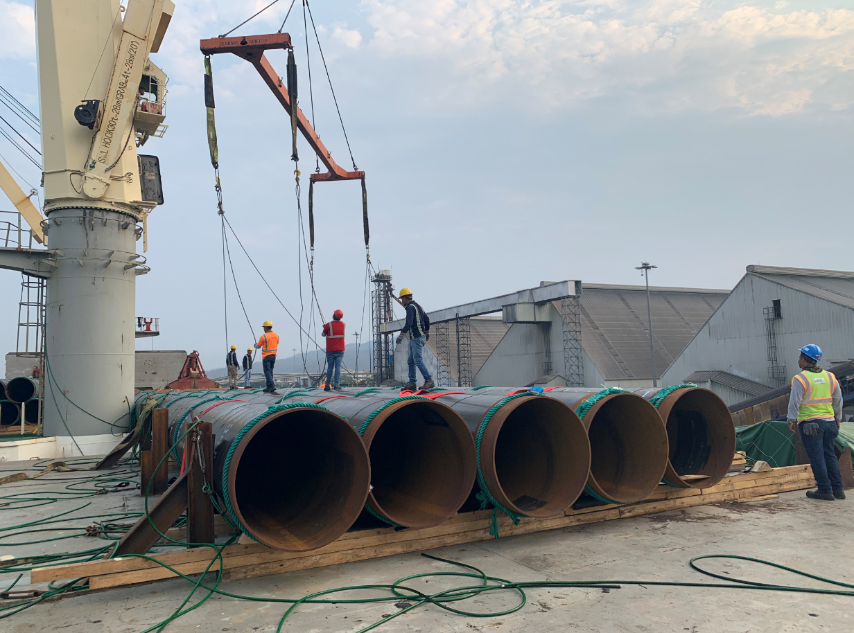
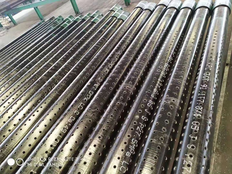
Steel Pipe Pile
Weld Connection Calculation
Full hand calculation & Midas modeling for φ630×10 pile · 6 weld types
✓ 1200 kN design axial
✓ 5 data tables
⚠ most ignored weld
design axial
pile dim.
weld types
critical weld
0. Engineering Pain Point: Missing Weld = Rework
In steel trestle design, structural focus is often placed on massive main elements—leaving secondary connection welds unchecked. A real field case: a φ630 pile splice extension with a defective butt weld cracked at a 12m driving depth, resulting in 7 days of site stoppage and an 80,000 RMB direct financial loss. Critically, standard practice typically reviews only 3 out of the 6 necessary structural weld types.
⚠ Shear ring welds (pile-to-cap configuration) are the most frequently omitted connections. Because they are cast into concrete and lack an explicit, simplified calculation formula in standard codes, they are routinely overlooked. Under heavy horizontal dynamic force distributions, they risk breaking first, inducing catastrophic pile pull-out failures.
1. Weld Connection Overview — 6 Typologies
From the bottom base up to the structural deck of a steel pipe pile system, six unique weld types act in unison to transmit variable load combinations across structural nodes.
| # | Weld Type | Structural Location | Force Characteristics | Code Basis |
|---|---|---|---|---|
| 1 | Butt Weld | Pile Extension Splice | Axial Force (N) | GB 50017 |
| 2 | Fillet Weld (Bracing) | Sway Bracing to Pile Face | Shear Stress (V) | GB 50017 |
| 3 | Flange Weld | Pile Top to Flange Interface | Combined N + M | GB 50017 |
| 4 | Stiffener Weld | Internal Ring Stiffeners | Concentrated Local Bearing | GB 50017 |
| 5 | Bracket Weld | Support Bracket to Outer Wall | Combined M + V | GB 50017 |
| 6 | Shear Ring Weld | Pile Outer Wall to Concrete Cap | Horizontal Shear + Uplift | JTG D62 (Implicit) |
1.1 Unified Design Parameters
| Parameter Descriptor | Design Value | Unit |
|---|---|---|
| Pipe Outer Diameter (D) | 630 | mm |
| Wall Thickness (t) | 10 | mm |
| Steel Base Material Grade | Q345 | — |
| Electrode Match Typology | E50 (\(f_f^w = 200 \text{ MPa}\)) | — |
| Design Axial Load (N) | 1200 | kN |
2. Butt Weld (Pile Extension Piece) — Circumferential Full Penetration
\(l_w = 1959.2\text{ mm}\)
\(\sigma = 61.2\text{ MPa}\)
Stress Ratio: 0.207
Governing Formula: \(\sigma = \frac{N}{l_w \cdot t} \le f_t^w \text{ or } f_c^w\). Utilizing a Class-1 full penetration setup, weld strength structurally matches the parent metal.
| Calculation Item | Structural Symbol | Evaluated Value |
|---|---|---|
| Weld Circumference (C) | \(\pi \cdot D\) | 1979.2 mm |
| Effective Weld Length (\(l_w\)) | \(C – 2t\) | 1959.2 mm |
| Calculated Normal Stress (\(\sigma\)) | \(N / (l_w \cdot t)\) | 61.2 MPa |
| Allowable Compressive Stress (\(f_c^w\)) | Q345 with E50 | 305 MPa ✓ Passes |
3. Fillet Weld (Sway Bracing Members) — Channel to Pipe Face
Governing Formula: \(\tau_f = \frac{V}{h_e \cdot l_w} \le \beta_f \cdot f_f^w\), where effective throat size is \(h_e = 0.7 h_f\). Modeled for standard [20a channel sections with 4 running lines of fillet configurations.
| Engineering Parameter | Evaluated Output Value |
|---|---|
| Applied Design Shear (V) | 180 kN |
| Effective Throat Thickness (\(h_e\)) | 5.6 mm |
| Total Combined Effective Throat Area (\(A_w\)) | 4121.6 mm² |
| Weld Shear Stress (\(\tau_f\)) | 43.7 MPa (< 200 MPa ✓ Passes) |
4. Flange Weld (Pile Top Connection) — Annular Fillet Setup
Governing Formula: \(\sigma_f = \frac{N}{A_w} + \frac{M}{W_w} \le \beta_f \cdot f_f^w\). Applied moment M = 450 kN·m represents the primary stress driver.
| Calculation Item | Resulting Value |
|---|---|
| Effective Weld Cross-Sectional Area (\(A_w\)) | 13,854.4 mm² |
| Effective Structural Section Modulus (\(W_w\)) | 2.18 × 10⁶ mm³ |
| Axial Component Stress (\(\sigma_N\)) | 86.6 MPa |
| Bending Component Stress (\(\sigma_M\)) | 206.2 MPa |
| Total Combined Welded Interface Stress (\(\sigma_f\)) | 119.6 MPa (Allowable: 244 MPa ✓ Passes) |
5. Stiffener Weld — Internal Ring Reinforcement
Utilizes four internal structural stiffener ring plates connected via continuous double fillet configurations. Operational stress levels track trace minimal values, but the configuration must remain to guarantee strict local geometric detailing regulations.
6. Bracket Weld — Combined M+V Loading (Critical Controlling Element)
Governing Formula: \(\sigma_{zs} = \sqrt{\sigma_M^2 + \tau_V^2} \le \beta_f \cdot f_f^w\). Evaluated for a 200×300 mm structural bracket plate utilizing continuous double fillet welds.
| Design Metric | Evaluated Value |
|---|---|
| Applied Transverse Shear Force (V) | 180 kN |
| Applied Primary Bending Moment (M) | 45 kN·m |
| Peak Bending Stress Component (\(\sigma_M\)) | 211.8 MPa |
| Shear Stress Component (\(\tau_V\)) | 20.9 MPa |
| Combined Equivalent Stress Vector (\(\sigma_{zs}\)) | 212.8 MPa (Allowable Limit: 244 MPa | Direct Safety Margin: 12.8%) |
Engineering Re-design Recommendation: Increase structural leg size \(h_f\) to 10 mm or extend total bracket depth profile up to 350 mm to expand long-term field safety thresholds.
7. Shear Ring Weld — Pile-to-Cap Interfacing (Most Commonly Omitted)
Governing Combined Formula: \(\sqrt{(\sigma_f / \beta_f)^2 + \tau_f^2} \le f_f^w\). Evaluated configuration assumes top and bottom boundary ring fillet welds running in unison.
| Design Criterion | Evaluated Value |
|---|---|
| Weld Leg Setup Length (\(h_f\)) | 8 mm (Continuous Dual-Ring Line Array) |
| Total Combined Throat Area (\(A_{w,\text{total}}\)) | 45,669 mm² |
| Horizontal Shear Force Stress (\(\tau_f\)) | 3.9 MPa |
| Uplift Extraction Tension Stress (\(\sigma_f\)) | 2.6 MPa |
| Combined Resultant Field Vector | 4.4 MPa (Allowable Capacity Limit: 200 MPa ✓ Passes) |
Do Not Disregard Trace Low Stresses: If field installation downscales leg sizes to \(h_f = 4\text{ mm}\) or structural uplift actions are underestimated during seismic shifts, localized failure vectors can develop rapidly. Always enforce field visual inspections.
8. Comprehensive Multi-Weld Performance Summary Matrix
| Identified Weld Connection | Peak Calculated Stress (MPa) | Code Allowable Limit (MPa) | Resulting Demand-Capacity Ratio | Remaining Structural Safety Margin |
|---|---|---|---|---|
| Butt Weld Splice | 61.2 | 305 | 0.207 | 79.3% |
| Fillet Bracing Weld | 43.7 | 200 | 0.219 | 78.1% |
| Annular Flange Connection | 119.6 | 244 | 0.490 | 51.0% |
| Internal Ring Stiffener | 1.5 | 244 | 0.006 | 99.4% |
| External Structural Bracket | 212.8 | 244 | 0.872 | 12.8% (Controlling) |
| Submerged Shear Ring | 4.4 | 200 | 0.022 | 97.8% |
9. Midas Modeling Applications — Finite Element Simulation Strategies
| FEM Modeling Strategy | Applicable Joint Configurations | Assumed Boundary Stiffness Input |
|---|---|---|
| Rigid Link Formulations | Butt Welds, Full-Penetration Splices | Infinite Rigidity Matrix |
| Elastic Link Element Attributes | Fillet Profiles, Flanges, Brackets, Shear Rings | \(K_s = G \cdot A_w / l_w\) |
| End-Release Degrees of Freedom | Partial Penetration Setup, Single-Side Fillets | Attenuated Rotational Stiffness Constraints |
Numerical Model Application (Flange Joint): Applying the elastic parameter expression gives: \(K_s = \frac{79,000 \cdot 13,854.4}{200} = 5.47 \times 10^6 \text{ kN/m}\). These computed linear results should be directly declared within the SDx, SDy, and SDz translation boundaries of the Midas Civil model properties.
10. Design Pitfall Guide — Avoid 6 Critical Calculation Errors
- ❌ Omitting the Shear Ring Matrix: Neglecting to perform verification checks on these sub-grade elements completely invalidates structural integrity safety reviews.
- ❌ Incorrect \(\beta_f\) Factor Allocation: Assigning a value of 1.22 instead of the standard 1.0 limit for side fillet configurations artificially inflates structural capacities.
- ❌ Failing to Deduct Arc Loss: Neglecting to calculate the \(2h_f\) start-stop arc reduction can falsely overstate a joint’s capacity by 5% to 15%.
- ❌ Isolating Bracket Shear Forces: Assessing pure vertical shear forces while ignoring concurrent bending actions falsely yields a low 0.105 ratio instead of the accurate 0.872 threshold.
- ❌ Welding Electrode Material Mismatch: Pairing Q345 base materials with a lower E43 electrode grade drops total structural node capacity by up to 25%.
- ❌ Overusing Infinite Rigid Links in FEM: Applying rigid link controls across every joint artifically stiffens structural behavior, understating internal stress factors by 20% to 30%.