EN 10210 Structural Steel Pipes: Hot Finished Structural Hollow Sections Complete Technical Directory
The Definitive Metallurgical, Geometric, and Tolerancing Index for EN 10210 Non-Alloy and Fine-Grain Structural Steel Hollow Sections. Comprehensive Chemical Profiles, Stress Capacity Weights, and Mechanical Verification Data.
2. Grade Nomenclature
3. Dimension Matrices
4. Chemical Compositions
5. Mechanical Metrics
6. Geometric Tolerances
7. Testing Protocols
8. Industrial Application
1. European Standard EN 10210: Scope & Processing Methodology
The European Standard EN 10210 specifies the technical delivery conditions for hot-finished structural hollow sections formed in circular, square, rectangular, or elliptical profiles. This specification covers structural tubes fabricated from non-alloy and fine-grain steel substrates intended for high-stress civil engineering infrastructures, offshore platforms, heavy crane frameworks, and dynamic mechanical loading systems.
The primary technological characteristic of EN 10210 hollow sections is their manufacturing process. These profiles are either formed hot to their final dimensions (with or without subsequent heat treatment) or formed cold with subsequent heat treatment. This post-forming heat treatment must meet or exceed the normalization temperature window, producing a uniform metallurgical structure equivalent to a hot-formed product.
This thermal processing profile removes internal residual manufacturing stresses found in standard cold-formed sections (such as EN 10219 tubes). Eliminating these localized stress concentrations balances structural yield characteristics across the cross-section, improves ductile performance in the corners of square and rectangular profiles, and provides reliable resilience against dynamic fatigue, bucking, and impact cracking.
Key Operational Advantages of Hot-Finished Hollow Profiles:
- Homogeneous Grain Structure: Normalization eliminates hazardous HAZ (Heat-Affected Zone) brittleness in longitudinally welded seams.
- Enhanced Section Properties: Thicker corners and uniform wall distributions provide up to 15% higher load capacities compared to cold-formed equivalents.
- Excellent Workability: Low residual stress allows for trouble-free oxy-fuel cutting, structural bending, and field welding without dimensional distortion.
Table 1: Technical Framework Overview & Production Scope
| Technical Parameter | EN 10210 Manufacturing Capability Boundaries |
|---|---|
| Primary Processes | Seamless (SMLS) / Electric Resistance Welded (ERW) / Submerged Arc Welded (SAW) with full inline normalization heat treatment loops |
| Core Steel Classifications | Non-Alloy Structural Steels (Part 1) & Normalized Fine-Grain Alloy Structural Steels (Part 2) |
| Available Core Grades | S235JRH, S275J0H, S275J2H, S355J0H, S355J2H, S355K2H, S275NH, S275NLH, S355NH, S355NLH, S420NH, S460NH |
| Structural End Finishing | Square Plain Ends (PE), Beveled Ends (BE) for weld prep, Threaded Coupling Ends, Grooved Ends |
| Surface Finish Options | Bare Mill Finish, Anti-Corrosive Black Vanish, Hot-Dip Galvanized (HDG), Fusion Bonded Epoxy (FBE), 3-Layer Polyethylene (3PE) |
2. Decoding EN 10210 Structural Grade Nomenclature
The structural steel grades specified in EN 10210 follow a standardized alphanumeric system that defines the material’s application class, yield performance limits, impact properties, and production methods.
Understanding this layout allows structural designers to select the appropriate grade based on operational conditions, minimum ambient temperature limits, and loading requirements.
Structural Coding Breakdown:
S Structural Steel Designation: Confirms the material is certified exclusively for structural and load-bearing designs.
355 Minimum Yield Point Matrix: Represents the minimum guaranteed yield strength ($R_{eH}$) in MPa ($1\text{ MPa} = 1\text{ N/mm}^2$) for section thicknesses $\le 16\text{ mm}$.
J2 Charpy V-Notch Impact Index: Specifies the testing criteria for minimum absorbed impact energy ($27\text{ Joules}$ minimum) across temperature profiles (e.g., J0 = $0^\circ\text{C}$, J2 = $-20^\circ\text{C}$, K2 = $-20^\circ\text{C}$ at $40\text{ Joules}$).
H Hollow Structural Profile Symbol: Identifies the product as a completed tubular section.
Table 2: Key Differences Between Structural Designations
| Steel Designation | EN Code | Impact Energy Threshold | Test Temperature | Core Mechanical Focus |
|---|---|---|---|---|
| S235JRH | 1.0039 | Min. 27 Joules | $+20^\circ\text{C}$ | General light framing; secondary load support. |
| S275J0H | 1.0149 | Min. 27 Joules | $0^\circ\text{C}$ | Medium-load infrastructure; balanced environmental use. |
| S275J2H | 1.0138 | Min. 27 Joules | $-20^\circ\text{C}$ | Sub-zero load safety; stable seismic frameworks. |
| S355J0H | 1.0547 | Min. 27 Joules | $0^\circ\text{C}$ | High-load commercial infrastructure, column pillars. |
| S355J2H | 1.0576 | Min. 27 Joules | $-20^\circ\text{C}$ | Standard high-stress bridge & maritime equipment components. |
| S355K2H | 1.0512 | Min. 40 Joules | $-20^\circ\text{C}$ | Extreme heavy dynamic duty; crane jibs, high-impact zones. |
3. Structural Profiles & Geometric Dimension Matrices
EN 10210 covers structural hollow sections across four main geometric profiles. Production capability extends from small, heavy-wall circular structural tubes up to large, thick-walled square and rectangular columns.
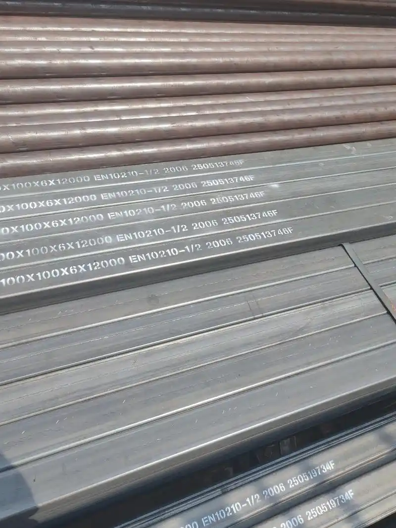
Table 3: Dimensional Envelope Boundaries by Shape Profile
| Section Profile Type | Maximum Outside Dimension | Maximum Available Wall Thickness ($T$) | Production Processing Option |
|---|---|---|---|
| Circular Hollow Sections (CHS) | Up to $\Phi\ 2500\text{ mm}$ | Up to $120.0\text{ mm}$ | Seamless / Submerged Arc Welded |
| Square Hollow Sections (SHS) | Up to $800\text{ mm} \times 800\text{ mm}$ | Up to $40.0\text{ mm}$ | ERW / Formed Hot / Welded Box Seam |
| Rectangular Hollow Sections (RHS) | Up to $750\text{ mm} \times 500\text{ mm}$ | Up to $40.0\text{ mm}$ | ERW / Seamless Mill Production |
| Elliptical Hollow Sections (EHS) | Up to $500\text{ mm} \times 250\text{ mm}$ | Up to $20.0\text{ mm}$ | Special Hot Profile Sizing Mill Loops |
4. Ultimate Chemical Composition Limit Matrices (Cast Analysis)
The chemical composition of EN 10210 steels is tightly controlled to balance mechanical strength with structural weldability. High carbon equivalents ($CEV$) can affect field welding by increasing the risk of cold cracking along the heat-affected zone.
The tables below outline chemical limitations for non-alloy structural steels (Part 1) and fine-grain structural alloys (Part 2).
Table 4: Non-Alloy Structural Steel Cast Analysis Limits (% by Mass, Maximum)
| Steel Grade Name | Deoxidation Type | Carbon (C) Thickness Window | Silicon (Si) | Manganese (Mn) | Phosphorus (P) | Sulfur (S) | Nitrogen (N) | |
|---|---|---|---|---|---|---|---|---|
| ≤ 40 mm | > 40 mm ≤ 120 mm | |||||||
| S235JRH | FN | 0.17 | 0.20 | – | 1.40 | 0.040 | 0.040 | 0.009 |
| S275J0H | FN | 0.20 | 0.22 | – | 1.50 | 0.035 | 0.035 | 0.009 |
| S275J2H | FF | 0.20 | 0.22 | – | 1.50 | 0.030 | 0.030 | – |
| S355J0H | FN | 0.22 | 0.22 | 0.55 | 1.60 | 0.035 | 0.035 | 0.009 |
| S355J2H / K2H | FF | 0.22 | 0.22 | 0.55 | 1.60 | 0.030 | 0.030 | – |
Table 5: Fine-Grain Structural Steel Cast Analysis Matrix (% by Mass, Maximum, Thickness < 65 mm)
| Grade Code | C max. | Si max. | Mn Scope | P max. | S max. | Al min. | Cr max. | Ni max. | Mo max. | Cu max. |
|---|---|---|---|---|---|---|---|---|---|---|
| S275NH / NLH | 0.20 | 0.40 | 0.50 – 1.40 | 0.035 | 0.030 | 0.020 | 0.30 | 0.30 | 0.10 | 0.35 |
| S355NH / NLH | 0.20 | 0.50 | 0.90 – 1.65 | 0.035 | 0.030 | 0.020 | 0.30 | 0.50 | 0.10 | 0.35 |
| S420NH / NLH | 0.22 | 0.60 | 1.00 – 1.70 | 0.035 | 0.030 | 0.020 | 0.30 | 0.80 | 0.10 | 0.70 |
| S460NH / NLH | 0.22 | 0.60 | 1.00 – 1.70 | 0.035 | 0.030 | 0.020 | 0.30 | 0.80 | 0.10 | 0.70 |
5. Mechanical Strength Performance & Material Limits
The mechanical configuration of an EN 10210 hollow structural section varies depending on the product’s wall thickness. As cross-sectional thickness increases, the material’s minimum yield point ($R_{eH}$) shifts downward due to differences in core reduction factors during rolling.
The following datasets provide the engineered tensile boundaries, yield minimums, and elongation properties required for structural designs.
Table 6: Non-Alloy Structural Steel Mechanical Properties Matrix
| Steel Grade Code | Minimum Yield Strength $R_{eH}$ (MPa) vs. Thickness ($T$) | Tensile Strength $R_m$ (MPa) | Min Elongation $A$ (%) | ||||
|---|---|---|---|---|---|---|---|
| ≤ 16 mm | 16 < $T$ ≤ 40 | 40 < $T$ ≤ 63 | 63 < $T$ ≤ 80 | ≤ 3 mm | 3 < $T$ ≤ 100 | ||
| S235JRH | 235 | 225 | 215 | 215 | 360 – 510 | 360 – 510 | 24% |
| S275J0H / J2H | 275 | 265 | 255 | 245 | 430 – 580 | 410 – 560 | 23% |
| S355J0H / J2H | 355 | 345 | 335 | 325 | 510 – 680 | 470 – 630 | 22% |
Table 7: Fine-Grain Structural Steel Mechanical Properties Matrix
| Steel Grade Designation | Min. Yield strength (≤16mm) | Tensile Band Range $R_m$ (MPa) | Min Long Elongation (%) | Charpy Impact Energy Metric |
|---|---|---|---|---|
| S275NH / NLH | 275 MPa | 370 – 510 | 24% | 40 J at $-20^\circ\text{C}$ / $-50^\circ\text{C}$ |
| S355NH / NLH | 355 MPa | 470 – 630 | 22% | 40 J at $-20^\circ\text{C}$ / $-50^\circ\text{C}$ |
| S420NH / NLH | 420 MPa | 520 – 680 | 19% | 40 J at $-20^\circ\text{C}$ / $-50^\circ\text{C}$ |
| S460NH / NLH | 460 MPa | 540 – 720 | 17% | 40 J at $-20^\circ\text{C}$ / $-50^\circ\text{C}$ |
6. Strict EN 10210 Structural Geometric Dimensional Tolerances
Hot-finished structural profiles feature tight geometric dimensional tolerances because their final shaping occurs while the steel is at an elevated temperature. This accurate thermal shaping minimizes wall thickness variations and profile twisting along the tube length.
Table 8: Profile Parameter Structural Deviations Matrix
| Structural Characteristic | Circular Hollow Cross-Sections | Square / Rectangular Cross-Sections |
|---|---|---|
| Outside Diameter / Dimensions ($D$) | ± 1% (Min ± 0.5 mm, Max ± 10 mm) | ± 1% (Min ± 0.5 mm) |
| Wall Thickness Deviation ($T$) | -10% Max Specified Limit | -10% Max Specified Limit |
| Out-of-Roundness (Ovality) | 2% max when diameter/thickness ratio ≤ 100 | – |
| Concavity / Convexity Limits | – | Max 1% of side length sizing profile |
| Straightness Profile Tolerance | ≤ 0.2% over total tube length run | ≤ 0.15% over total tube length run |
| Total Delivered Mass Tolerance | ± 6% on individual lengths | ± 6% on individual lengths |
Table 9: Delivery Length Deviations & Permissible Variances
| Length Selection Style | Standard Structural Dimensions (mm) | Permissible Compliance Tolerance Window |
|---|---|---|
| Random Structural Lengths | $4000 \le L \le 16000\text{ mm}$ | 10% of sections may fall below minimum ordered range, but cannot measure shorter than 75% of minimum specification. |
| Approximate Structural Lengths | $4000 \le L \le 16000\text{ mm}$ | ± 500 mm |
| Exact Length Base (≤6000) | $2000 \le L \le 6000\text{ mm}$ | +10 / -0 mm |
| Exact Length Base (>6000) | $6000 \le L \le 18000\text{ mm}$ | +15 / -0 mm |
7. Mechanical Validation & Quality Inspection Protocols
Compliance with the EN 10210 standard requires a strict validation protocol to confirm the structural performance of each production lot. Material certification under EN 10204 Type 3.1 or 3.2 inspection certificates depends on successfully passing these material tests.
Table 10: Mandatory vs. Optional Inspection Operations
| Testing Target | Testing Operational Verification Scope | Compliance Status |
|---|---|---|
| Cast Chemical Analysis | Spectrographic tracking of elemental mass percentages per manufacturing batch heat. | Mandatory Certification |
| Tensile Testing | Destructive testing to measure material yield strength ($R_{eH}$), tensile capacity ($R_m$), and elongation metrics. | Mandatory Certification |
| Charpy Impact Test | V-notch test tracking fracture energy limits across controlled temperature ranges. (Excludes S235JRH if thickness ≤ 6mm). | Mandatory Certification |
| Weld NDT Tracking | Continuous non-destructive testing (Eddy Current, Ultrasonic, or X-ray) along longitudinally welded profiles. | Mandatory for Welded Sections |
| Product Analysis | Independent chemical re-testing performed directly on sample pieces taken from completed hollow sections. | Optional Client Agreement |
8. Industrial Application Fields & Structural Environments
Because of their structural homogeneity and low internal stresses, EN 10210 hot-finished structural hollow sections are utilized across several demanding construction and engineering fields.
Table 11: Application Positions & Grade Suitability Choices
| Infrastructure Field | Specific Equipment Position & Stress Use Details | Preferred Recommended Grade |
|---|---|---|
| Heavy Civil Construction | Load-bearing bridge pillars, high-rise support columns, airport terminal frameworks, trusses, and wide-span roof structures. | S355J2H / S355NH |
| Marine & Offshore Projects | Offshore platform jacket structures, deep-water heliport supports, mooring piles, and coastal defense frameworks exposed to wave action. | S355NLH / S420NLH |
| Mechanical Equipment | Mobile container crane jibs, high-capacity material handling chassis, structural mining components, and agricultural machine bases. | S355K2H / S460NH |
⚠️ METALLURGICAL SUBSTITUTION DIRECTIVE:
Substituting cold-finished EN 10219 sections for hot-finished EN 10210 profiles without re-evaluating the engineering design can compromise safety. Cold-finished tubes contain higher internal residual stresses along their corners, which alters fatigue limits and response under seismic or dynamic loads. Always confirm the required processing method matches the design specification.
Optimize Your Structural Safety Coefficients With EN 10210 Hot-Finished Hollow Sections
Ensure uniform load distribution, material trace verification, and reliable performance under low temperatures by sourcing certified structural hollow sections.
Technical Resource Document ID: EN10210-HOT-FINISHED-INDEXED-2026 | Approved For Global Search Engine Structural Reference Distribution.
9. Advanced Structural Bending Mechanics & Cross-Sectional Performance
When engineering long-span trusses, columns, and frameworks under complex axial compression or bending moments, calculation of cross-sectional properties is critical. EN 10210 hot-finished sections possess superior resistance to local buckling compared to cold-formed alternatives. This behavior stems from their uniform grain distribution and the complete absence of high internal stresses across the corner transition regions.
Structural designers calculating load capacity must analyze the secondary moment of inertia ($I$), elastic section modulus ($W_{el}$), and plastic section modulus ($W_{pl}$). Due to the hot-finishing process, square and rectangular sections maintain a tighter, more predictable exterior corner radius matrix, typically bounded by $r_o \le 2.0T$ (where $T$ represents nominal wall thickness). This allows for full-plastic design optimization under Eurocode 3 standard limits.
Table 12: Mechanical Sizing Profiles vs. Structural Calculation Formulas
| Profile Classification | Critical Evaluation Parameter | Hot-Finished Behavior Limit | Eurocode 3 Class Rating |
|---|---|---|---|
| Square Sections (SHS) Up to $400 \times 400 \times 16\text{ mm}$ |
Radius Uniformity Coefficient ($r_o$) | 1.5T to 2.0T Max | Class 1 (Plastic) |
| Torsional Sizing Factor ($I_t$) | Full continuous distribution | ||
| Rectangular Sections (RHS) Up to $500 \times 300 \times 20\text{ mm}$ |
Bending Axis Deflection ($I_y / I_z$) | Symmetric ± 1.0% Var. | Class 1 / Class 2 |
| Web Slenderness Metric ($h/t$) | Highly stable under shear | ||
| Circular Sections (CHS) Up to $\Phi\ 610 \times 32\text{ mm}$ |
Local Buckling Ratio ($D/t$) | Compliant under axial load | Class 1 (Compact) |
| Wall Variation Allowance | ≤ 8.0% eccentric offset |
10. Comprehensive Linear Weight & Cross-Sectional Dimension Data
Accurate estimation of raw linear weight per meter ($M$) is critical for logistical execution and structural framework dead-load calculations. The calculations for structural hollow profiles follow the European volumetric density metric for carbon steel profiles, precisely calibrated to $7.85\text{ kg/dm}^3$.
Hot-finished manufacturing ensures a uniform wall thickness distribution, meaning actual weight matches theoretical calculations closely. This allows for tighter tolerances on heavy foundation pile structures or tall crane frame setups.
Table 13: Core Square Sizing Profile Theoretical Weight Matrix
| Outside Sizing Profile ($B \times H, \text{mm}$) | Nominal Wall Thickness ($T, \text{mm}$) | Cross-Sectional Area ($A, \text{cm}^2$) | Theoretical Unit Weight ($M, \text{kg/m}$) |
|---|---|---|---|
| $100 \times 100$ | 6.3 | 23.40 | 18.40 |
| 8.0 | 28.90 | 22.70 | |
| 10.0 | 34.70 | 27.20 | |
| $200 \times 200$ | 8.0 | 60.90 | 47.80 |
| 12.5 | 92.00 | 72.20 | |
| 16.0 | 114.00 | 89.60 | |
| $400 \times 400$ | 10.0 | 155.00 | 121.00 |
| 16.0 | 242.00 | 190.00 | |
| 20.0 | 297.00 | 233.00 |
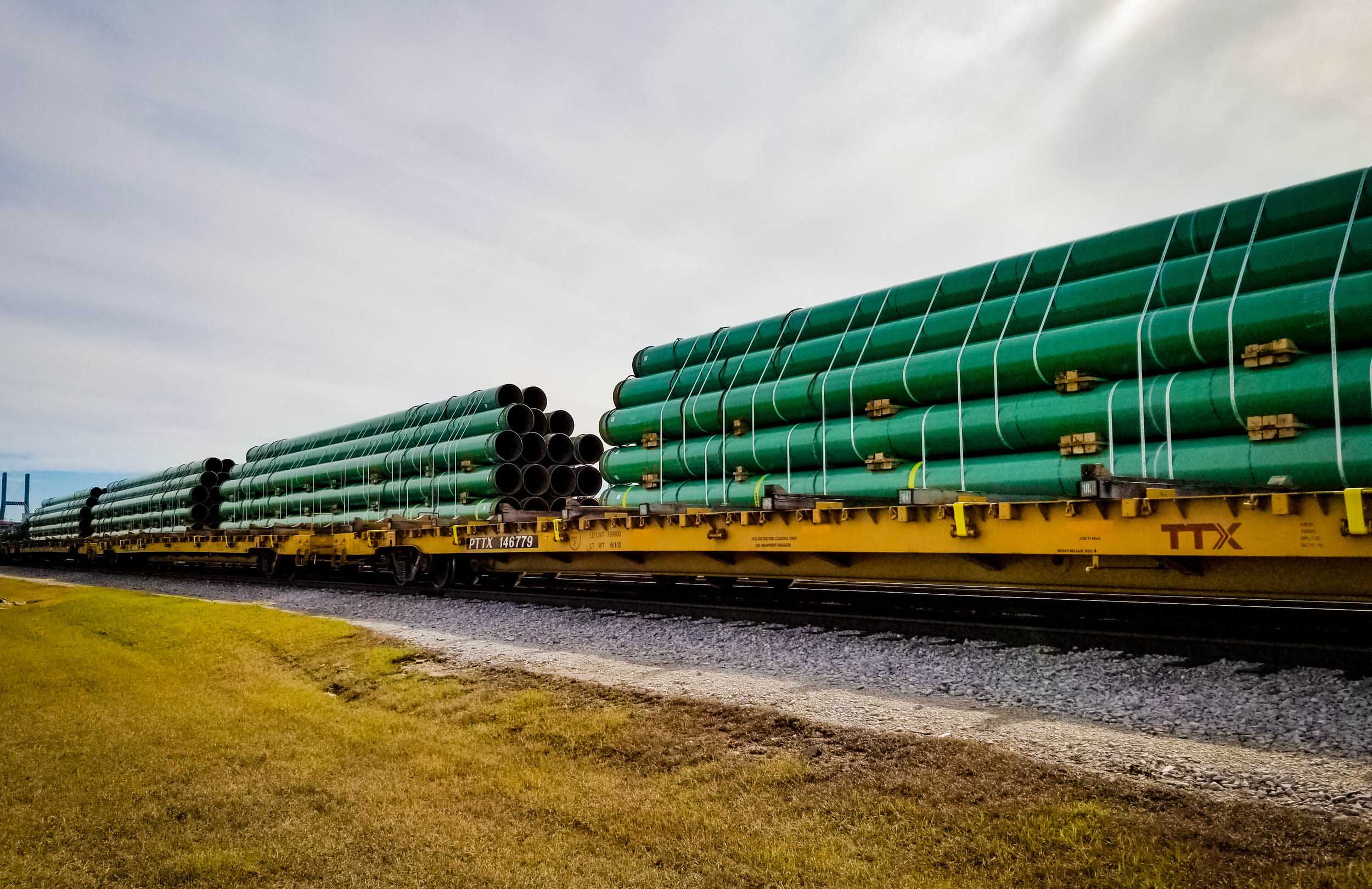
11. Surface Integrity, Corrosion Control & Specialized Coatings
To ensure an extended operational service life in challenging environments, EN 10210 profiles can be specified with post-rolling surface modifications. For industrial infrastructure, maritime structures, and chemical processing facilities, applying a durable barrier coating prevents oxidative corrosion and localized chemical breakdown.
Selecting a suitable coating protocol is directly guided by the target environment classification, following the ISO 12944 standard (ranging from standard inland conditions to extreme C5-M marine environments). For high-integrity pipeline loops or heavy framing elements, executing a controlled abrasive blast cleaning stage (minimum Sa 2.5 standard) ensures a rough profile profile anchor necessary for coating adhesion.
Table 14: Surface Treatment Protocols & Corrosion Protection Specs
| Coating Type | Processing Parameters & Application Layer Detail | Target Layer Thickness ($\mu\text{m}$) |
|---|---|---|
| Hot-Dip Galvanizing (HDG) | Full mechanical immersion in a molten zinc bath at temperatures around $450^\circ\text{C}$ per EN ISO 1461. Creates a durable metallurgical iron-zinc alloy layer. | $55\ \mu\text{m} – 85\ \mu\text{m}$ min |
| Fusion Bonded Epoxy (FBE) | Electrostatic application of dry epoxy powder onto pipes pre-heated to $220^\circ\text{C}$ to $240^\circ\text{C}$. Provides a seamless chemical barrier against ground corrosion. | $300\ \mu\text{m} – 500\ \mu\text{m}$ |
| 3-Layer Polyethylene (3PE) | A high-performance multi-layer system consisting of a high-performance primer layer, a copolymer adhesive bonding agent, and a thick outer polyethylene top-coat. | $\ge 1.8 – 3.5\text{ mm}$ total |
| Anti-Corrosive Varnish | A temporary surface-applied liquid oil layer applied to prevent flash rust during transoceanic shipping or warehouse storage. Easily stripped prior to site welding. | $15\ \mu\text{m} – 25\ \mu\text{m}$ |
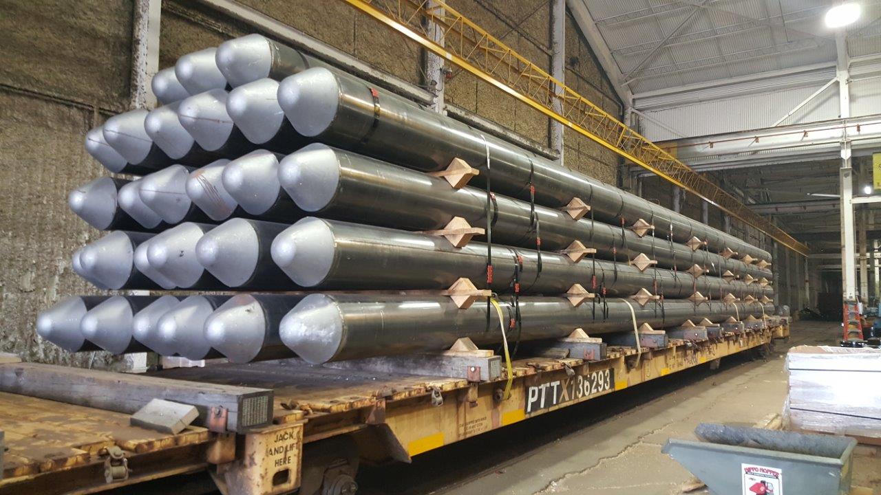
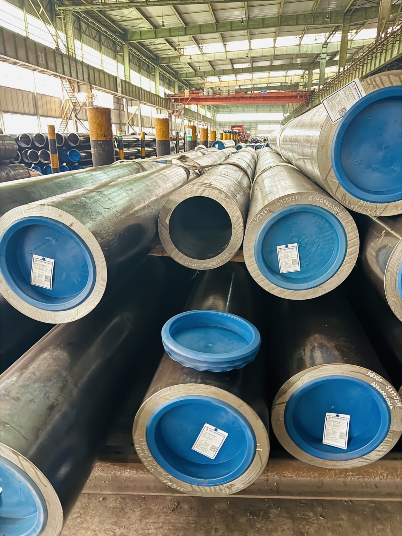
12. Logistics Management, Stacking Guidelines & On-Site Storage Protocols
Preserving the straightness tolerances and edge profiles of heavy-walled hollow structural sections requires strict adherence to proper handling procedures during transport and warehouse storage. Due to the high linear weights of large-diameter profiles, improper nesting or stacking can distort tube geometry or damage protective surface coatings.
Bundles should be supported by wood dunnage strips positioned to prevent point-load concentrations that can cause local sagging. Additionally, beveled pipe ends should be protected with heavy composite plastic end caps to prevent edge damage prior to site preparation.
Table 15: Storage Limits & Transport Stacking Matrix
| Profile Shape Group | Recommended Structural Nesting & Handling Methods | Maximum Safe Stack Tiers |
|---|---|---|
| Small Circular (≤ Φ 114.3mm) | Hexagonal shipping bundles tightly bound with heavy high-tensile steel straps. Lift using nylon slings to protect material surfaces. | Max 12 Tiers High |
| Large Square Columns (≥ 300x300mm) | Block stacking format with seasoned timber spacing strips layered between row profiles. Align corners vertically to ensure straight load paths. | Max 4 Tiers High |
| Thick-Walled Heavy SMLS Pile Sections | Pyramid stacking configuration secured with heavy steel side chocks or locking pins to prevent shifting. Do not use metal chains directly on bare steel. | Dependent on ground limits |