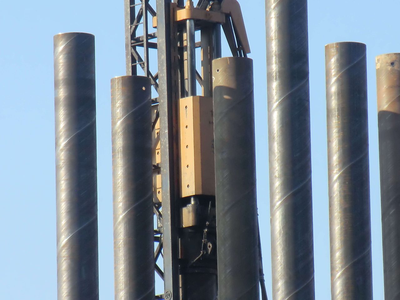
The engineering of a slotted liner for sand control in petroleum and geothermal wells represents one of the most intriguing paradoxes in structural mechanics. We are, essentially, taking a perfectly engineered pressure vessel—a seamless steel pipe—and systematically weakening it by cutting hundreds or thousands of longitudinal apertures into its body. The research into the mechanical properties of these slotted liners is not merely a study of material strength, but an exploration of the limits of structural stability under the complex, triaxial loading of the subterranean world.
The Inner Monologue of the Structural Engineer
When I consider the slotted liner, I am not seeing a static filter. I am seeing a dynamic component subjected to the immense tectonic forces of the earth. The moment we introduce a “slot” into the steel, we are fundamentally altering the stress distribution. We create stress concentrations at the ends of the slots—areas where the molecular lattice is stretched to its limit. In my mind, I see the flow of stress lines around these apertures, like water flowing around an island in a river. The tighter the slot, the faster the “flow” of stress, leading to potential yielding long before the bulk material reaches its theoretical limit.
We must account for the loss of the moment of inertia. By removing material, we reduce the pipe’s resistance to bending and, more critically, to collapse. In deep-sea or high-pressure reservoirs, the external hydrostatic pressure is trying to crush this “weakened” cylinder. The research must therefore bridge the gap between pure filtration efficiency (which demands more and larger slots) and structural survival (which demands as much intact steel as possible).
Material Foundation and the Slotted Geometry
To analyze the mechanical behavior, we must first define the baseline. Most high-tier slotted liners are derived from API 5L or API 5CT grades, such as N80, L80, or P110. The choice of material is the first line of defense. A higher yield strength allows for more aggressive slotting patterns, but it often comes at the cost of fracture toughness.
The slots themselves are usually cut via laser or high-speed milling. Laser cutting, while precise, introduces a Heat Affected Zone (HAZ) at the edge of the slot. This zone is a metallurgical minefield—locally hardened, potentially brittle, and a prime candidate for crack initiation during the massive thermal expansion cycles seen in Steam Assisted Gravity Drainage (SAGD) wells.
Comparative Geometric and Material Benchmarks
| Parameter | Symbol | Unit | Typical Range (Heavy Duty) | Impact on Performance |
| Yield Strength | $\sigma_s$ | MPa | 552 – 862 (N80 to P110) | Determines the baseline for elastic deformation. |
| Slot Length | $L_s$ | mm | 50 – 80 | Longer slots significantly reduce axial stiffness. |
| Slot Width | $W_s$ | mm | 0.15 – 3.0 | Controls sand retention but affects flow velocity. |
| Slot Density | $n$ | slots/m | 100 – 600 | Directly proportional to the “Strength Reduction Factor.” |
| Residual Stress | $\sigma_r$ | MPa | 50 – 150 | Introduced during cutting; can accelerate fatigue. |
The Mechanics of Collapse: The Vulnerability of the Void
The most critical test for any slotted liner is the external pressure collapse test. In a solid pipe, the collapse pressure is a function of the $D/t$ ratio (Diameter to thickness). In a slotted liner, we must introduce a “Strength Reduction Factor” ($k$).
Research indicates that the collapse resistance of a slotted liner ($P_{sc}$) can be modeled as:
where $\phi$ represents the opening ratio (the percentage of removed surface area) and $\alpha$ is an empirical coefficient derived from experimental data that accounts for the “slot staggering” effect.
Experimental data suggests that staggered slot patterns—where the slots in adjacent rows do not align horizontally—significantly outperform aligned patterns. This is because a staggered pattern prevents the formation of a continuous “weak path” around the circumference of the pipe. When we subject these liners to physical testing in a high-pressure autoclave, the failure mode is almost always a localized buckling that originates at the center of the longest slot row.
Tensile and Torsional Integrity
While collapse is the primary concern for service life, tensile strength is the primary concern for installation. A liner must support its own weight, often several kilometers long, as it is lowered into the wellbore.
The tensile efficiency of a slotted liner is generally higher than its collapse efficiency. This is because the cross-sectional area of the steel remains relatively high if the slots are longitudinal. However, if the slots have a slight “keystone” or trapezoidal profile (wider on the inside to prevent sand plugging), the effective wall thickness is reduced.
In horizontal wells, torsional strength becomes the bottleneck. As the pipe is rotated to overcome friction during “running-in,” the slots act as torsional springs. If the torque exceeds the elastic limit of the slot ends, the slots will “twist,” leading to permanent deformation and potentially closing the slots entirely or opening them so wide that sand control is lost.
Experimental Strength Retention Data (Example Study)
| Pattern Type | Opening Ratio (%) | Tensile Retention (%) | Collapse Retention (%) | Torsional Retention (%) |
| Straight Row | 2.5 | 88 | 72 | 65 |
| Staggered | 2.5 | 92 | 84 | 78 |
| Overlapping | 3.5 | 82 | 61 | 54 |
Thermal Mechanics and the SAGD Challenge
In thermal recovery projects like SAGD, the slotted liner is subjected to temperatures exceeding 250°C. The steel expands, but because it is often constrained by the formation or the cement, it undergoes “thermal buckling.”
The mechanical research here moves into the realm of Elasto-Plasticity. At these temperatures, the yield strength of the P110 or L80 steel drops significantly. The slots become sites for localized plastic strain concentration. Our experimental research involving cyclic thermal loading has shown that the “tips” of the slots undergo low-cycle fatigue. After several dozen steam-injection cycles, micro-cracks emerge from the slot radii. This is why modern high-performance slotted liners now utilize “Stress Relief Radii”—circular or elliptical ends to the slots—rather than sharp corners, to lower the Stress Intensity Factor ($K$).
The Fluid-Structure Interaction (FSI)
We cannot study the mechanics of the pipe in a vacuum. The flow of oil, gas, and sand through the slots creates an erosion-corrosion environment. As sand particles strike the edges of the slots, they “hone” the steel, slowly increasing the slot width and removing the protective passive film of the alloy.
Advanced research now uses CFD (Computational Fluid Dynamics) coupled with FEA (Finite Element Analysis) to model this. We find that as the slot erodes, the structural integrity of the pipe degrades over time. A pipe that was safe at Year 1 may collapse at Year 5 not because of increased external pressure, but because the “steel bridges” between the slots have been thinned by the constant sandpaper-like action of the reservoir fluids.
Conclusion and the Path Forward: Smart and Resilient Liners
The future of slotted liner research lies in the optimization of the “Bridge-to-Slot” ratio. We are seeing a move toward Bimetallic Slotted Liners, where a high-strength carbon steel outer shell provides the mechanical backbone, while a thin, corrosion-resistant alloy (CRA) liner or coating protects the slots from erosion.
Furthermore, the integration of Distributed Fiber Optic Sensing (DFOS) along the length of the slotted liner allows us to monitor the mechanical strain in real-time. We can now “hear” the pipe beginning to buckle or “feel” the temperature-induced stress before a catastrophic failure occurs.
The study of slotted liners is a testament to the fact that in engineering, a hole is not just an absence of matter; it is a presence of complexity. By understanding the mechanical nuances of these apertures, we ensure that the “weakest link” in the wellbore is strong enough to withstand the weight of the world.
The use of pipe piles in foundation construction has been a popular choice for many years. Pipe piles are used to transfer the load of a structure to a deeper, more stable layer of soil or rock.
Benefits of Pipe Trusses The use of pipe trusses in construction offers several notable advantages: Strength and Load-bearing Capacity: Pipe trusses are renowned for their high strength-to-weight ratio. The interconnected pipes distribute loads evenly, resulting in a sturdy and reliable structure. This allows for the construction of large spans without the need for excessive support columns or beams.
The standard for fluid-conveying seamless pipes depends on the country or region you are in, as well as the specific application. However, some widely used international standards for fluid-conveying seamless pipes are: ASTM A106: This is a standard specification for seamless carbon steel pipes for high-temperature service in the United States. It is commonly used in power plants, refineries, and other industrial applications where high temperatures and pressures are present. It covers pipes in grades A, B, and C, with varying mechanical properties depending on the grade. API 5L: This is a standard specification for line pipes used in the oil and gas industry. It covers seamless and welded steel pipes for pipeline transportation systems, including pipes for conveying gas, water, and oil. API 5L pipes are available in various grades, such as X42, X52, X60, and X65, depending on the material properties and application requirements. ASTM A53: This is a standard specification for seamless and welded black and hot-dipped galvanized steel pipes used in various industries, including fluid-conveying applications. It covers pipes in two grades, A and B, with different mechanical properties and intended uses. DIN 2448 / EN 10216: These are European standards for seamless steel pipes used in fluid-conveying applications, including water, gas, and other fluids. Read more
Fluid-conveying seamless pipes are designed to resist various types of corrosion depending on the material used and the specific application. Some of the most common types of corrosion that these pipes are designed to resist include: Uniform corrosion: This is the most common type of corrosion, where the entire surface of the pipe corrodes uniformly. To resist this type of corrosion, pipes are often made of corrosion-resistant materials, such as stainless steel or lined with protective coatings. Galvanic corrosion: This occurs when two dissimilar metals are in contact with each other in the presence of an electrolyte, leading to the corrosion of the more active metal. To prevent galvanic corrosion, pipes can be made of similar metals, or they can be isolated from each other using insulating materials or coatings. Pitting corrosion: Pitting is a localized form of corrosion that occurs when small areas on the pipe's surface become more susceptible to attack, leading to the formation of small pits. This type of corrosion can be prevented by using materials with high pitting resistance, such as stainless steel alloys with added molybdenum, or by applying protective coatings. Crevice corrosion: Crevice corrosion occurs in narrow spaces or gaps between two surfaces, such Read more

Wedge wire screens, also known as profile wire screens, are commonly used in various industries for their superior screening capabilities. They are constructed from triangular-shaped wire,
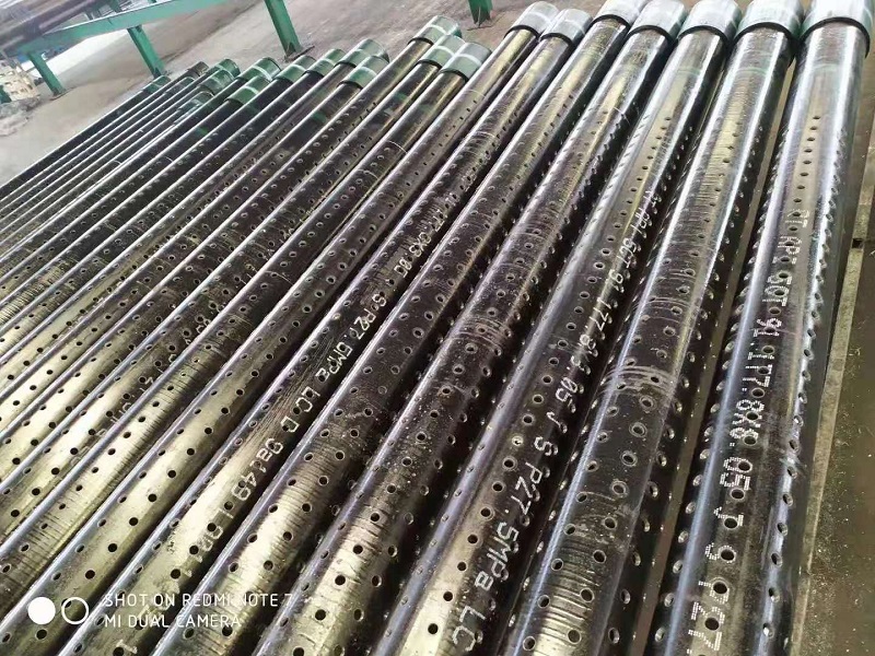
2 7/8in J55 K55 Perforated Well Casing Pipe is one of mainly products of we abter steel, they can be used for water, oil, gas well drilling fields. The thicknesss can be supplied from 5.51-11.18mm based on client's well depth and required mechanical properties. Normally they are provided with thread connection, like NUE or EUE, which will be easier to installed at site. The length of 3-12m perforated casing pipes are available for client's different drilling rigs height. The hole diameter and open area on the surface are also customized. The popular hole diameters are 9mm, 12mm, 15mm, 16mm, 19mm, etc.
