Research on the Influence of Welds on the Stress of Steel Pipe Piles During Pile Driving
Introduction
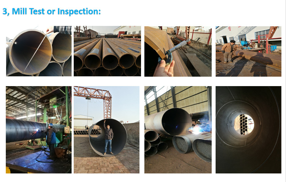
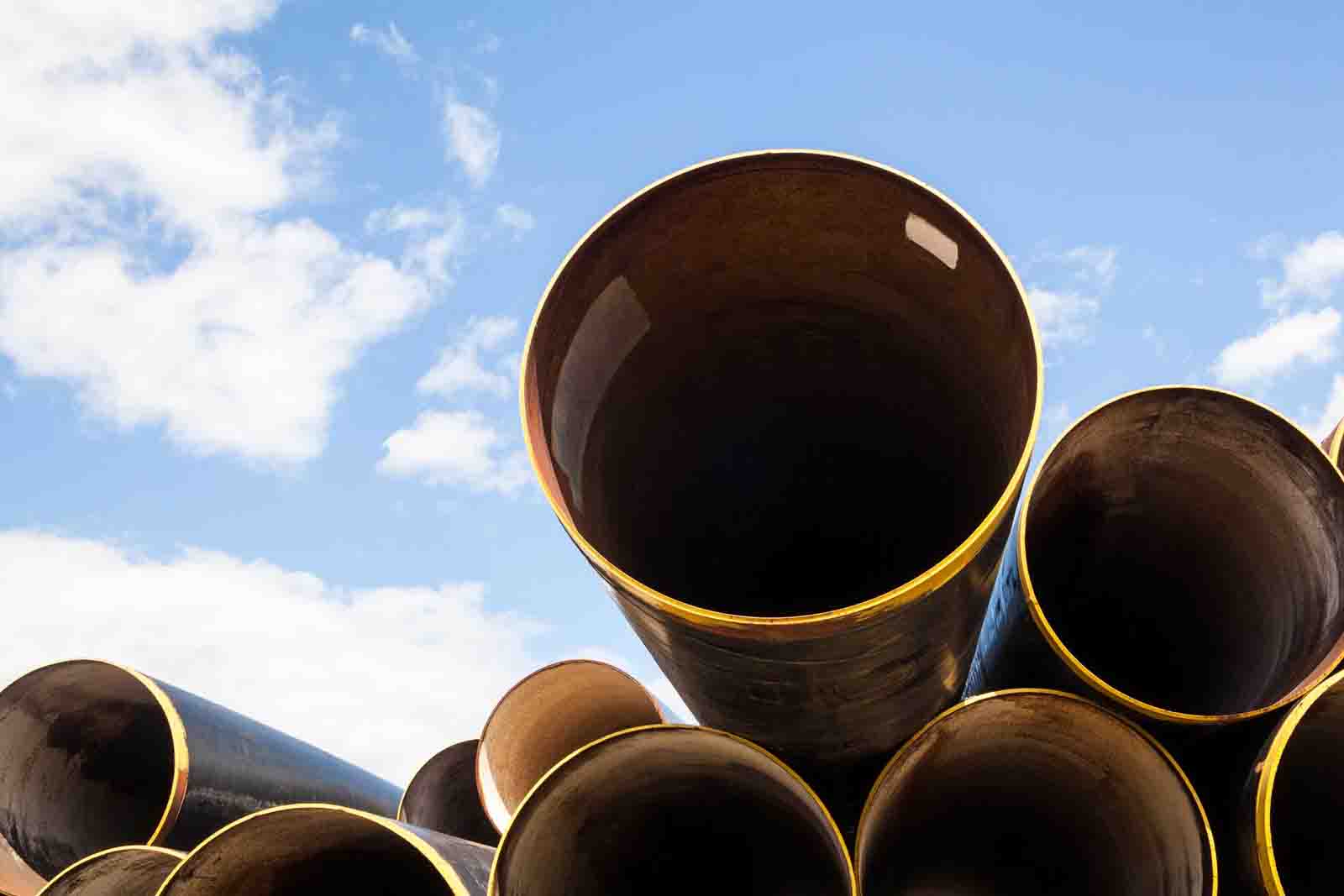
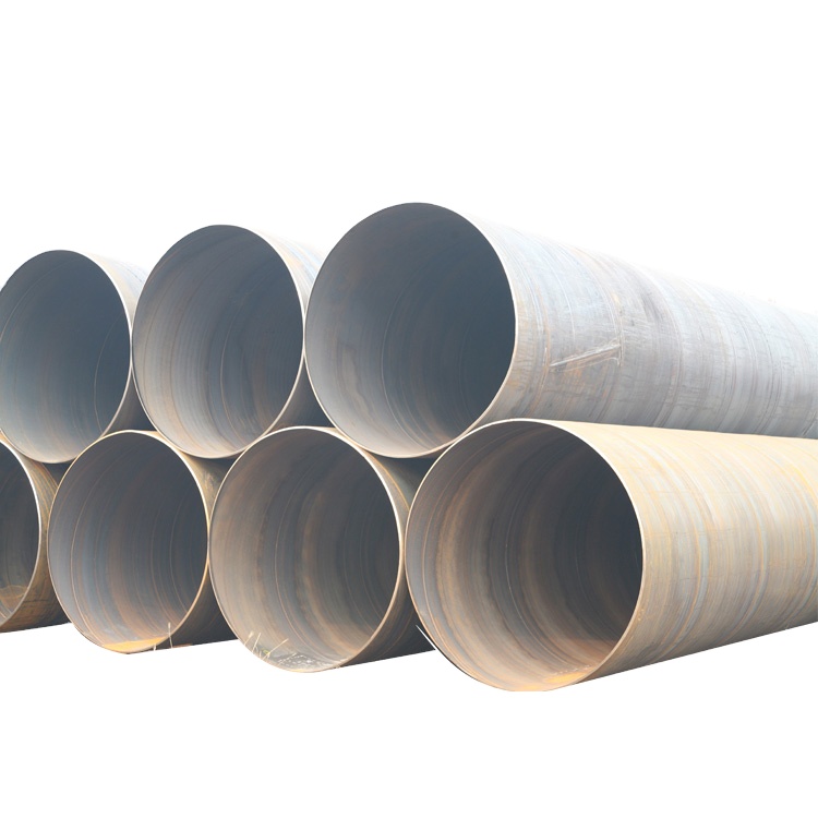
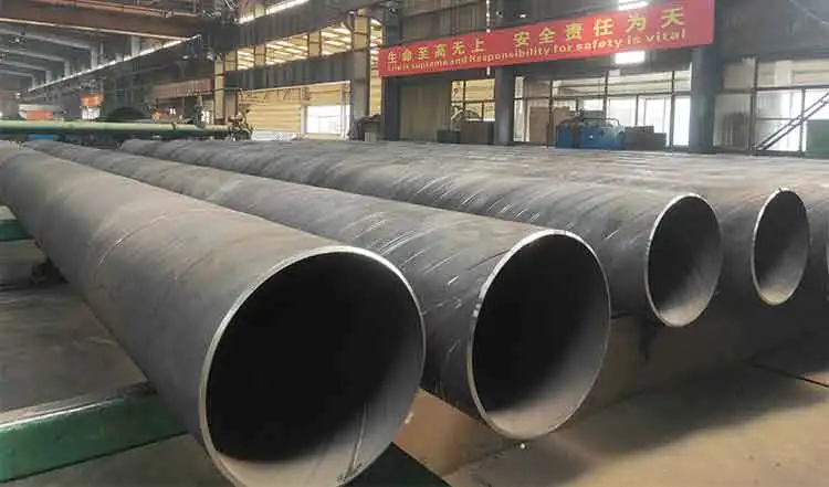
Steel pipe piles are widely used in civil engineering projects, particularly in offshore foundations, bridge construction, and high-rise buildings. These piles are driven into the ground using impact hammers, a process that subjects them to significant dynamic stresses. Often, steel pipe piles are fabricated or extended by welding multiple sections together, introducing welds as critical points of concern. Welds, while necessary for achieving the desired pile length, can significantly alter the stress distribution and structural integrity of the pile during driving. Imperfections in welds, residual stresses from the welding process, and the dynamic loading during pile driving can exacerbate stress concentrations, potentially leading to fatigue, cracking, or failure.
This research explores the influence of welds on the stress of steel pipe piles during pile driving, focusing on stress distribution, concentration at weld regions, fatigue behavior, and practical mitigation strategies. Through theoretical analysis, numerical modeling, and case studies, the study aims to provide a comprehensive understanding of weld-related effects and propose methods to enhance pile performance.
Theoretical Background
Mechanics of Pile Driving
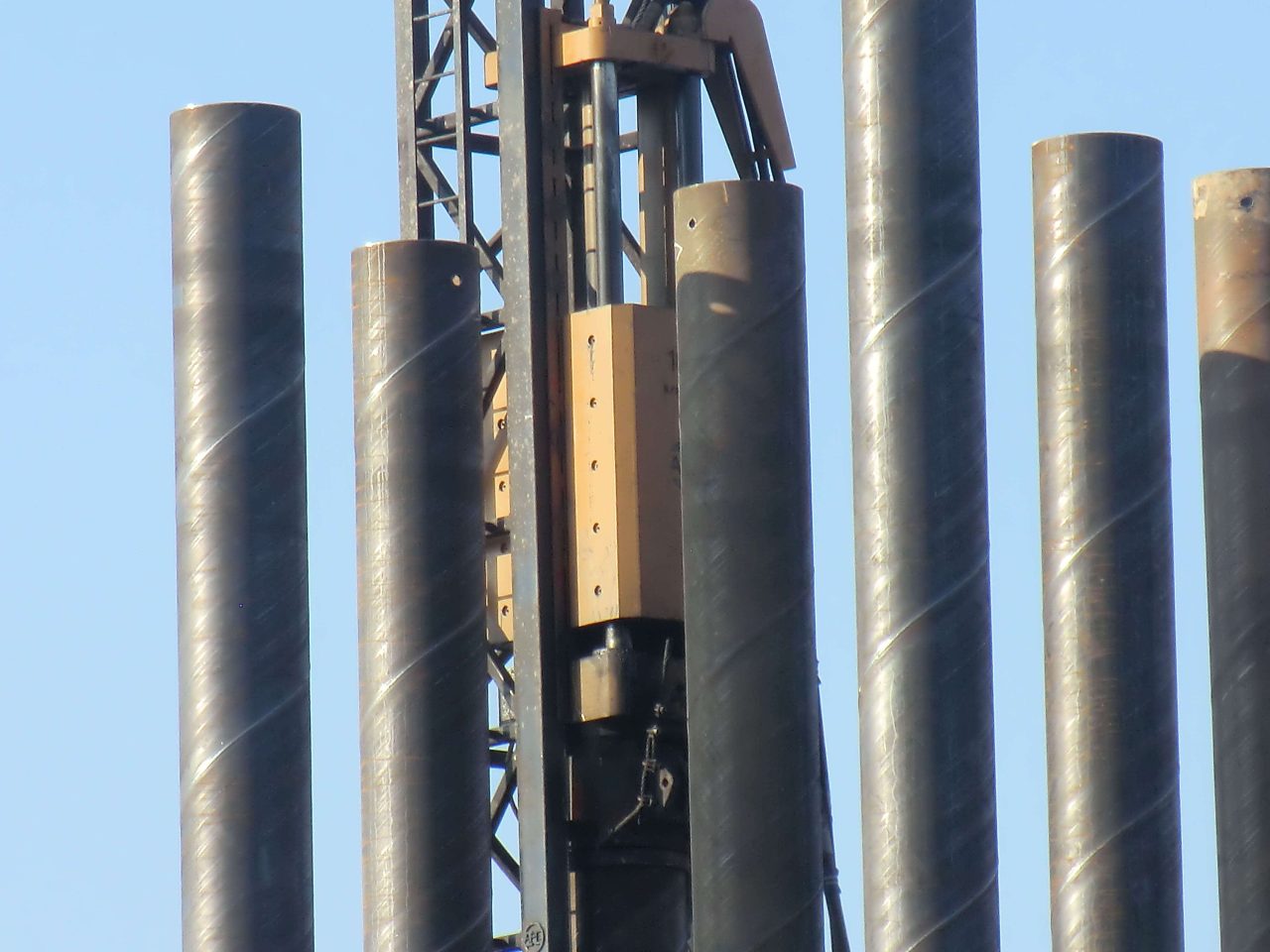
Pile driving involves the use of impact hammers to impart kinetic energy to the pile, forcing it into the ground. This process generates a compressive stress wave that propagates along the pile length. The stress wave reflects at boundaries (e.g., the pile tip or discontinuities like welds), leading to complex stress states. The primary stresses during pile driving include:
- Axial Compressive Stress: Generated by the hammer impact.
- Tensile Stress: Resulting from wave reflections, particularly in hard soils where the pile tip encounters high resistance.
- Shear Stress: Induced by lateral soil resistance or misalignment during driving.
- Bending Stress: Occurring if the pile is not perfectly vertical or if lateral loads are present.
The maximum stress in a pile during driving can be approximated using the one-dimensional wave equation:
Where:
- σmax: Maximum stress (Pa)
- E: Modulus of elasticity of steel (typically 210 GPa)
- A: Cross-sectional area of the pile (m2)
- vimp: Impact velocity of the hammer (m/s)
- c: Wave speed in steel, c = √(E / ρ), where ρ is the density of steel (~7850 kg/m3)
For a typical steel pipe pile with a wave speed of approximately 5100 m/s, even a moderate impact velocity (e.g., 5 m/s) can generate stresses exceeding 500 MPa, approaching or exceeding the yield strength of many steel grades.
Weld Imperfections and Their Role in Stress Distribution
Welds introduce several factors that influence stress during pile driving:
- Geometric Discontinuities: Weld beads, even when ground flush, create localized changes in the pile’s cross-section, leading to stress concentrations.
- Residual Stresses: The welding process induces residual stresses due to thermal expansion and contraction, often approaching the yield strength of the material.
- Material Heterogeneity: The heat-affected zone (HAZ) adjacent to the weld exhibits altered mechanical properties, such as reduced ductility or increased hardness, which can affect stress distribution.
- Weld Imperfections: Defects like porosity, slag inclusions, or incomplete penetration weaken the weld and increase stress concentrations.
The stress concentration factor (SCF) at a weld can be defined as:
Where:
- σmax, weld: Maximum stress at the weld
- σnominal: Nominal stress in the pile away from the weld
Typical SCF values for welds in steel pipe piles range from 1.5 to 3, depending on the weld quality and geometry.
Stress Analysis in Welded Steel Pipe Piles
Stress Distribution Along the Pile
During pile driving, the stress wave propagates as a compressive pulse from the pile head to the tip. At a weld, the wave encounters a discontinuity, leading to partial reflection and transmission. The reflected wave can create tensile stresses, especially if the weld is near the pile tip or in a region of high impedance mismatch.
Consider a steel pipe pile with a girth weld (circumferential weld joining two sections). The impedance Z of the pile is given by:
A mismatch in impedance at the weld (e.g., due to a thicker weld bead or material differences in the HAZ) causes wave reflection. The reflection coefficient R is:
Where Z1 and Z2 are the impedances on either side of the weld. A non-zero R indicates partial reflection, contributing to tensile stresses that can initiate cracking at the weld.
Stress Concentration at Welds
The presence of a weld increases local stresses due to geometric and material discontinuities. For a girth weld, the stress concentration is most pronounced at the weld toe, where the transition between the weld metal and base material occurs. Finite element analysis (FEA) studies indicate that the SCF at the weld toe can be as high as 2.5 for a typical manual weld, and up to 3.0 for welds with significant undercut or mismatch.
Table 1 provides typical SCF values for different weld conditions in steel pipe piles, based on empirical and numerical studies.
| Weld Condition | SCF Range | Notes |
|---|---|---|
| Perfect Weld (Ground Flush) | 1.2–1.5 | Minimal geometric discontinuity |
| Manual Weld (As-Welded) | 1.8–2.5 | Weld bead and slight mismatch |
| Weld with Undercut | 2.0–3.0 | Significant stress riser at weld toe |
| Weld with Misalignment | 2.5–3.5 | Additional bending stress due to offset |
Residual Stresses from Welding
Welding introduces residual stresses due to the thermal cycle of heating and cooling. These stresses are typically tensile in the weld and HAZ, balanced by compressive stresses in the surrounding base material. For a girth weld in a steel pipe pile, the peak residual stress can approach the yield strength of the steel (e.g., 350–500 MPa for common grades like S355).
During pile driving, these residual stresses superimpose on the dynamic stresses, potentially pushing the total stress beyond the material’s yield or ultimate tensile strength. The combined stress σtotal can be approximated as:
Where σdynamic is the stress from pile driving, and σresidual is the pre-existing residual stress. If σtotal exceeds the material’s fatigue limit, crack initiation becomes likely.
Numerical Modeling of Weld Effects
Finite Element Analysis (FEA) Approach
To quantify the influence of welds on stress during pile driving, finite element analysis (FEA) is employed. A typical FEA model includes the following components:
- Geometry: A 3D model of the steel pipe pile with a girth weld, including the weld bead, HAZ, and base material.
- Material Properties: Elastic-plastic behavior for steel, with distinct properties for the weld metal and HAZ.
- Boundary Conditions: A dynamic load applied at the pile head to simulate hammer impact.
- Weld Imperfections: Modeled as geometric discontinuities (e.g., undercut) or material defects (e.g., reduced toughness in the HAZ).
Case Study: FEA of a Welded Steel Pipe Pile
Consider a steel pipe pile with the following properties:
- Diameter: 1.2 m
- Wall thickness: 25 mm
- Material: S355 steel (yield strength 355 MPa, ultimate tensile strength 510 MPa)
- Weld type: Girth weld, manual, with slight undercut (SCF = 2.5)
The pile is driven into a medium-dense sand layer using a 10-tonne hammer with an impact velocity of 4 m/s. The FEA model uses a dynamic explicit solver to simulate the stress wave propagation.
Results
- Stress Distribution: The maximum dynamic stress in the pile away from the weld is approximately 450 MPa (compressive). At the weld toe, the stress peaks at 1125 MPa due to the SCF of 2.5.
- Wave Reflection: The weld causes a 15% reflection of the stress wave, leading to a tensile stress of 70 MPa immediately after the compressive pulse.
- Fatigue Implications: The cyclic nature of pile driving (thousands of hammer blows) induces fatigue damage, with the weld toe being the most vulnerable location due to high stress concentrations.
Table 2 summarizes the FEA results for different weld conditions.
| Weld Condition | Max Stress at Weld Toe (MPa) | Tensile Stress from Reflection (MPa) | Fatigue Life (Cycles) |
|---|---|---|---|
| Perfect Weld | 600 | 50 | 106 |
| Manual Weld (As-Welded) | 900 | 65 | 105 |
| Weld with Undercut | 1125 | 70 | 104 |
Parametric Study
A parametric study was conducted to evaluate the influence of weld geometry, material properties, and driving conditions on stress. Key findings include:
- Weld Geometry: Smoother weld profiles (e.g., ground flush) reduce the SCF and increase fatigue life by 50–100%.
- Material Properties: Higher toughness in the HAZ (e.g., achieved through post-weld heat treatment) reduces crack initiation risk.
- Driving Conditions: Lower impact velocities reduce peak stresses but may increase the number of blows required, potentially worsening fatigue damage.
Fatigue Behavior at Welds During Pile Driving
Fatigue Mechanism
Pile driving is inherently cyclic, with each hammer blow representing a stress cycle. Welds are particularly susceptible to fatigue due to:
- High Stress Concentrations: As shown in Table 1, SCFs at welds amplify the stress range.
- Residual Stresses: Tensile residual stresses lower the mean stress threshold for crack initiation.
- Material Variability: The HAZ often has reduced fatigue resistance due to microstructural changes.
The fatigue life N of a welded joint can be estimated using the S-N curve approach:
Where:
- Δσ: Stress range (MPa)
- C: Fatigue strength coefficient (material-dependent)
- m: Fatigue exponent (typically 3–5 for steel welds)
For a typical weld in S355 steel, C might be 100 MPa, and m = 3. With a stress range of 200 MPa (considering dynamic and residual stresses), the fatigue life is approximately 125,000 cycles, which may be exceeded in hard driving conditions.
Influence of Weld Imperfections
Weld imperfections such as undercut, porosity, or lack of fusion act as crack initiators, significantly reducing fatigue life. For example, an undercut weld with an SCF of 3.0 can reduce the fatigue life by an order of magnitude compared to a perfect weld, as shown in Table 2.
Practical Implications and Mitigation Strategies
Weld Quality Control
To minimize the adverse effects of welds on stress during pile driving, rigorous quality control is essential:
- Weld Inspection: Use non-destructive testing (NDT) methods like ultrasonic testing to detect defects.
- Weld Geometry: Grind welds flush to reduce stress concentrations.
- Post-Weld Heat Treatment (PWHT): Apply PWHT to relieve residual stresses, particularly for thick-walled piles.
Design Considerations
Designers can mitigate weld-related issues by:
- Optimizing Weld Placement: Position welds away from high-stress regions, such as near the pile tip where reflections are strongest.
- Selecting Weld Type: Use full-penetration butt welds instead of fillet welds for better load transfer.
- Material Selection: Choose steel grades with high toughness and fatigue resistance for the HAZ.
Driving Techniques
Adjusting pile driving techniques can also reduce stress at welds:
- Lower Impact Energy: Use smaller hammer blows to reduce peak stresses, though this increases the number of cycles.
- Cushioning: Employ pile cushions to dampen the impact energy, reducing stress wave amplitude.
- Monitoring: Use dynamic pile monitoring (e.g., Pile Driving Analyzer) to measure stresses in real-time and adjust driving parameters.
Table 3 summarizes recommended practices for mitigating weld-related stress issues.
| Strategy | Description | Expected Benefit |
|---|---|---|
| Weld Grinding | Smooth weld surface to reduce SCF | 20–50% reduction in SCF |
| PWHT | Heat treat to relieve residual stresses | 30–60% reduction in residual stress |
| NDT | Inspect welds for defects | Early detection of crack initiators |
| Optimized Weld Placement | Avoid welds near pile tip or high-stress zones | 10–20% reduction in peak stress |
Case Studies
Case Study 1: Offshore Wind Turbine Foundation
An offshore wind turbine foundation used large-diameter steel pipe piles (2 m diameter, 30 mm wall thickness) driven into a sandy seabed. The piles were extended using girth welds. During driving, cracking was observed at several welds, attributed to high stress concentrations (SCF ~2.8) and tensile residual stresses (~400 MPa). FEA revealed peak stresses at the weld toe exceeding 1000 MPa. Mitigation involved grinding the welds flush and applying PWHT, which reduced the SCF to 1.5 and eliminated cracking.
Case Study 2: Bridge Foundation in Hard Clay
A bridge foundation project used steel pipe piles (1 m diameter, 20 mm wall thickness) driven into hard clay. The welds exhibited fatigue damage after 8000 blows, with cracks initiating in the HAZ. Dynamic monitoring showed tensile stresses of 80 MPa due to wave reflections at the welds. Adjusting the hammer energy and using a pile cushion reduced the stress range by 25%, extending the fatigue life sufficiently to complete driving without failure.
Conclusion
Welds significantly influence the stress behavior of steel pipe piles during pile driving, primarily through stress concentrations, residual stresses, and wave reflection effects. The stress concentration factor at welds can amplify dynamic stresses by 1.5–3.5 times, while residual stresses from welding superimpose on these loads, increasing the risk of fatigue and cracking. Numerical modeling, such as FEA, provides a powerful tool to quantify these effects, revealing peak stresses at weld toes that often exceed the material’s yield strength. Fatigue analysis indicates that welds are the most vulnerable locations for crack initiation, particularly in the presence of imperfections like undercut or misalignment.
Practical mitigation strategies, including improved weld quality, optimized driving techniques, and careful design considerations, can significantly reduce the adverse effects of welds. Case studies demonstrate that these strategies are effective in real-world applications, ensuring the structural integrity of welded steel pipe piles under the harsh conditions of pile driving.