The analysis of the Laser Slotted Screen Pipe—a product encompassing Seamless (SMLS) and Electric Resistance Welded (ERW) configurations, designed for use across Drill Pipe, Casing, and Well Screen applications—requires a deliberate, expansive deep dive into material science, manufacturing physics, and petroleum engineering. This is not merely a pipe; it is a meticulously engineered structural and filtration component whose performance dictates the longevity and profitability of a subterranean asset, demanding a level of technical rigor that transcends simple standardization.
The genesis of this product lies in the fundamental challenge of reservoir management: sand control. Many productive formations, particularly unconsolidated sandstones, lack the cementation strength to withstand the pressure drawdowns inherent in fluid extraction, leading to the migration of fine particulate matter that rapidly erodes downhole tools, plugs flow lines, and requires expensive workovers. The Laser Slotted Screen Pipe addresses this by transforming a structural tubular, defined by $text{API 5CT}$ or $text{API 5DP}$ specifications, into a passive mechanical filter. The starting point for this transformation is the selection of the base pipe, a choice that immediately separates into two divergent manufacturing methodologies: the structurally homogenous Seamless (SMLS) pipe and the dimensionally precise Electric Resistance Welded (ERW) pipe. SMLS pipe, forged from a solid billet through processes like the Mannesmann mill, inherently boasts superior isotropy and through-wall integrity, making it the non-negotiable choice for applications demanding the highest collapse resistance (critical for deep wells) and the maximum resistance to corrosion or stress cracking, particularly when high-strength grades like $\text{P110}$ or specialized sour service grades such as $\text{T95}$ are mandated, where the potential failure of a weld seam, even one that is fully normalized, presents an unacceptable risk profile. This inherent material integrity makes SMLS the default premium choice, its microstructure having been thoroughly refined by extensive hot working, which often translates to superior toughness and a more predictable response to the subsequent localized thermal impact of laser cutting.
Conversely, the use of ERW pipe as a foundation is driven by its exceptional dimensional uniformity, particularly its near-perfect wall thickness consistency and its lower manufacturing cost, allowing for a more economical product when the application’s pressure and corrosive risk profile permits. The quality of a modern $\text{ERW}$ pipe intended for well service is defined by the integrity of the longitudinal weld seam, which must undergo rigorous non-destructive testing ($\text{NDT}$), including ultrasonic inspection ($\text{UT}$) of the entire weld line, and often a full-body normalizing or tempering heat treatment to homogenize the microstructure of the weld and its surrounding Heat Affected Zone ($\text{HAZ}$), ensuring it meets the mechanical and corrosion resistance parity of the parent metal, thereby making it suitable for lower-strength $\text{API}$ grades like $\text{J55}$ or $\text{K55}$ casing strings. The technical decision between $\text{SMLS}$ and $\text{ERW}$ must therefore be an exhaustive, risk-based analysis, weighing the intrinsic structural assurance of the seamless process against the economic and dimensional advantages of the welded alternative, a decision amplified by the fact that the subsequent laser slotting process will introduce a geometric stress riser that magnifies any pre-existing material discontinuity or microstructural weakness.
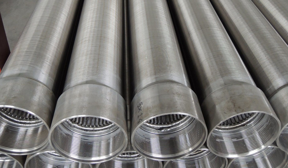
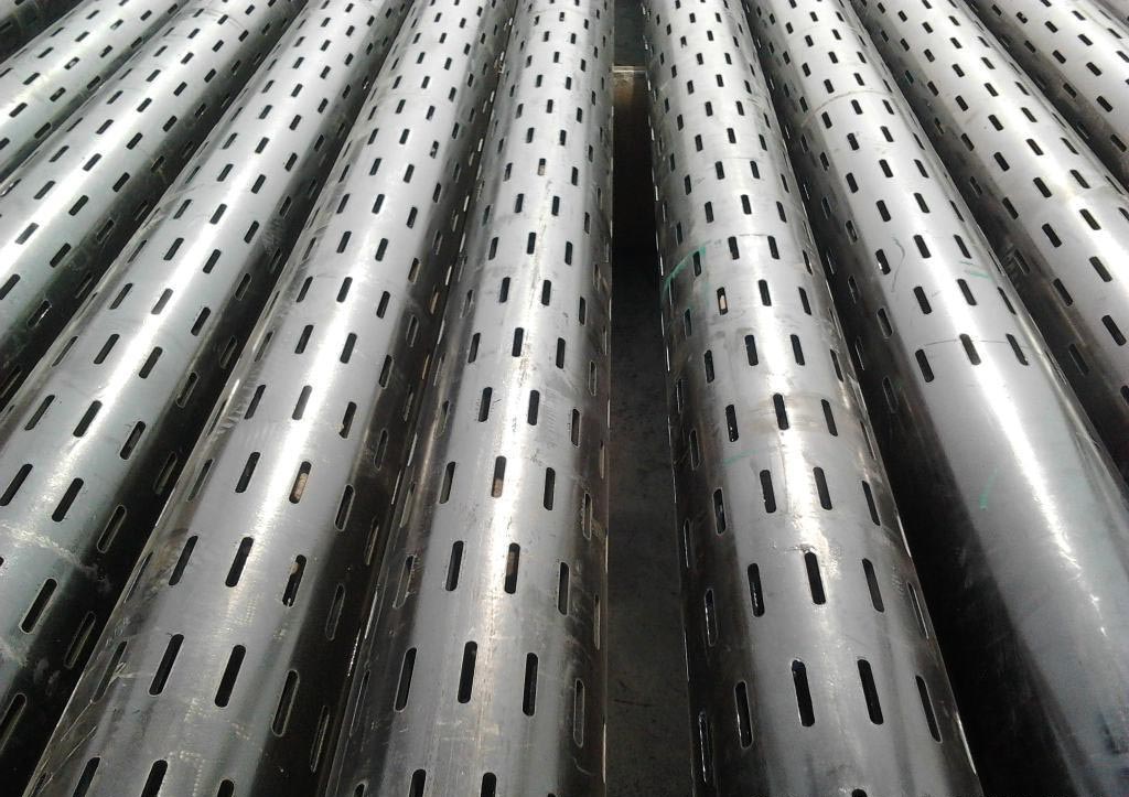
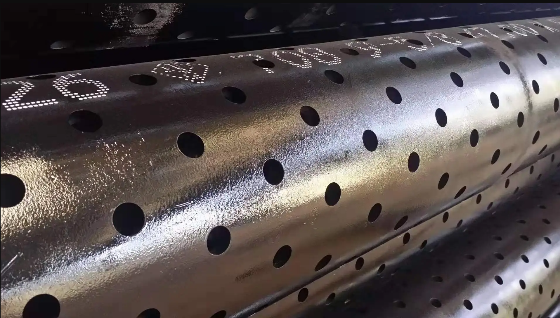
The core technology that defines this product is the Laser Slotting Process, a method that utilizes focused, high-energy light beams—typically $\text{CO}_2$ or fiber lasers—under precise Computer Numerical Control ($\text{CNC}$) to ablate and melt the steel along a predefined geometric path. This process offers immense technical superiority over older mechanical slotting techniques (like milling or punching) primarily in two critical domains: precision and slot geometry. The required Slot Width (Gauge), which is the direct particle control mechanism, is determined by the $\text{D}_{50}$ or $\text{D}_{10}$ particle size distribution of the reservoir sand, demanding a level of accuracy often measured in tens of microns ($\pm 0.05 \text{ mm}$ or better). The laser’s ability to maintain this micron-level tolerance across thousands of slots over the pipe’s length is crucial, as an undersized slot restricts flow, while an oversized slot fails the sand control function entirely.
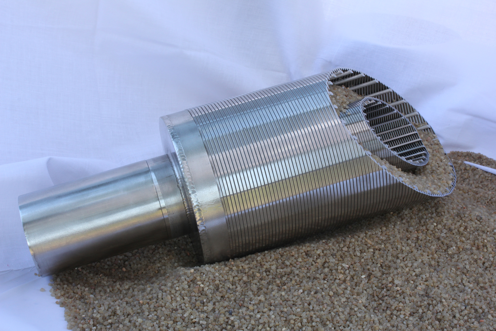
Beyond simple dimensional accuracy, the laser enables the creation of the essential Keystone Slot Geometry, where the width of the slot at the external surface is intentionally made narrower than the width at the internal surface, creating a subtle taper through the wall thickness. This critical feature is designed to prevent sand particles that successfully navigate the narrow entrance from lodging within the slot—a condition known as bridging or plugging—which would lead to rapid reduction in the screen’s Open Area Ratio and catastrophic pressure drop across the filter. The physics of the laser cut allows this precise tapering, which is immensely difficult to achieve with conventional mechanical tools, establishing the technical superiority of the laser-slotted pipe as an engineered filtration mechanism. However, this process introduces a localized thermal challenge: the formation of a shallow $\text{HAZ}$ around the slot edges. In high-strength steels, particularly those with a higher **Carbon Equivalent ($\text{CE}$) **, this rapid thermal cycle can locally induce the formation of brittle, untempered martensite or other hard phases, acting as a geometric and microstructural stress concentration factor ($\text{SCF}$) that could compromise the pipe’s resistance to tensile or collapse failure. Therefore, the laser parameters—power, pulse rate, and feed speed—must be rigorously qualified for each specific $\text{API}$ grade to ensure that the microhardness in the $\text{HAZ}$ does not exceed safe thresholds, a quality check that often requires specialized micro-hardness mapping across the slot section.
The base material selection is inextricably linked to the operational environment, dictating the necessity for materials compliant with NACE MR0175/ISO 15156 for corrosive wells containing hydrogen sulfide ($\text{H}_2\text{S}$). This necessity mandates the use of controlled yield strength materials like L80 (Type 1 or 9Cr) or T95, where the chemical composition—specifically the minimization of sulfur ($\text{S}$) and phosphorus ($\text{P}$) content—and the strict control of final hardness (typically capped at $23 \text{ HRC}$ for $\text{L80}$) are non-negotiable requirements to prevent Sulfide Stress Cracking (SSC). The challenge for the laser slotting process is proving that the localized heating and subsequent self-quenching does not locally increase the hardness in the $\text{HAZ}$ above the $\text{NACE}$ limit, thereby creating localized regions prone to brittle fracture under stress. A comprehensive supplier must provide certification that the slotting process has been validated through rigorous $\text{SSC}$ tests (e.g., four-point bend tests in $\text{H}_2\text{S}$ solution) on actual slotted samples, confirming that the integrity of the sour service grade is maintained post-fabrication, a critical technical step that distinguishes a high-quality product from one that risks catastrophic failure downhole.
The structural function of the pipe, especially when used as Casing or Drill Pipe, imposes immense Tensile Requirements and Collapse Resistance demands, which are directly defined by the chosen $\text{API}$ grade’s Yield Strength ($S_y$) and Tensile Strength ($S_u$). The pipe must possess sufficient tensile capacity to support its own weight, that of the completion string, and the frictional drag during running. Simultaneously, it must resist the massive external hydrostatic and formation pressures, which necessitate high collapse resistance ($\text{P}_c$). The introduction of the laser slots, by removing material, inherently reduces both the tensile cross-sectional area and the pipe’s stiffness, requiring a scientifically derived Derating Factor to be applied to the pipe’s nominal $\text{P}_c$. The design of the slot pattern, specifically the width and orientation of the remaining material bridges that resist the hoop stresses, becomes a critical structural engineering exercise. The bridges must be sufficient to maintain the required load capacity, often requiring strategic slot arrangements that prioritize circumferential strength preservation to ensure the pipe meets its designed collapse resistance rating in its slotted configuration. The entire structural analysis pivots on the final, reduced moment of inertia and cross-sectional area, making the selection of the base pipe wall thickness, and the supplier’s strict adherence to a tight negative $\text{Tolerance of Thickness Schedules}$, paramount for predictable performance.
The Heat Treatment Requirements are directly tied to the achievement of the specified $\text{API}$ grade properties. Grades like N80, L80, and P110 necessitate Quenching and Tempering ($\text{Q\&T}$) to achieve a uniform, high-strength tempered martensite or bainite microstructure. This $\text{Q\&T}$ process is performed on the entire pipe body before the slotting operation. The $\text{Q\&T}$ process is what sets the high Yield Strength and guarantees the necessary ductility (as measured by Elongation requirements), providing the material with the ability to yield locally without brittle fracture during the high-stress phases of installation and operation. If the laser slotting operation is found to induce unacceptable hardness in the $\text{HAZ}$ of a $\text{NACE}$ grade (like $\text{L80}$), a localized post-slotting tempering or stress-relief heat treatment might be required on the slotted section only, a costly and complex procedure that highlights the tight interdependence between material metallurgy and the screening fabrication technique. The detailed $\text{Chemical Composition}$ requirements of the base pipe—particularly the precise limits on carbon ($\text{C}$), manganese ($\text{Mn}$), and micro-alloying elements (vanadium, niobium, titanium)—are what enable the effective response to the $\text{Q\&T}$ treatment, ensuring that the high strength is achieved without compromising the pipe’s intrinsic toughness.
The Governing Standards for this product are multifaceted. The primary structure is $\text{API 5CT}$ for casing/tubing or $\text{API 5DP}$ for drill pipe, dictating the manufacturing quality, $\text{NDT}$ methods (e.g., $\text{EMI}$ and $\text{UT}$), and the dimensional tolerances for the pipe body and the essential threaded connections (which must be terminated well clear of the slotted area). However, the functional performance is cross-referenced by standards like ISO 17824 (Sand Screen Design and Qualification), which provides guidelines for the testing of the filtration efficiency and the calculation of $\text{P}_c$ derating factors. The final product Specification is therefore a hybrid document, incorporating the $\text{API}$ material certificate alongside the manufacturer’s proprietary Slotting Specification detailing the specific Slot Width Tolerance ($\pm 0.025 \text{ mm}$ for premium products), the number of slots per foot, the Keystone Angle, and the resulting $\text{Open Area Ratio}$. This open area ratio, while seeming simple, is the direct mathematical link to the pipe’s hydraulic capacity, requiring high-precision measurement and often verification via Computational Fluid Dynamics (CFD) modeling to predict the pressure drop under turbulent flow conditions in the well. The complexity lies in ensuring the dimensional tolerances of the $\text{API}$ pipe are sufficiently tight, often specifying pipe with a wall thickness tolerance much stricter than the $\text{API}$ minimum ($\text{e.g., } -6.25\% \text{ vs. } -12.5\%$), to guarantee that the final $\text{bridge}$ thickness is predictable, a crucial, non-standard requirement driven entirely by the $\text{Application}$ performance.
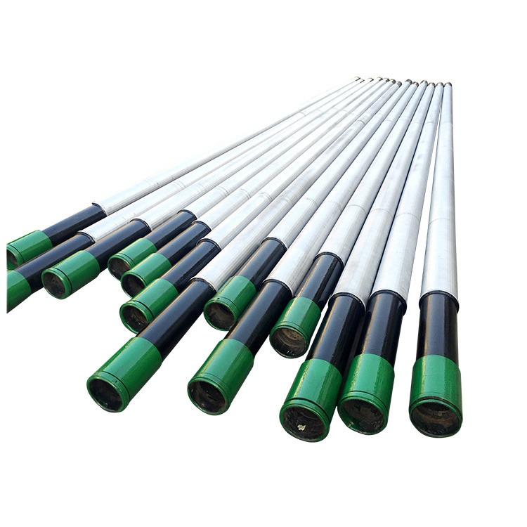
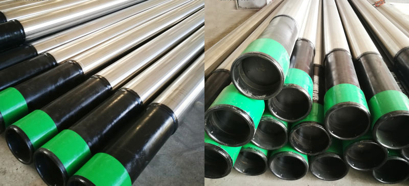
The Features of the Laser Slotted Screen Pipe ultimately converge on its single-piece construction, which translates directly into superior running strength and torsional stability compared to composite or wire-wrapped screens, which are susceptible to damage during aggressive installation procedures in long, highly deviated, or horizontal wellbores. Its inherent robustness minimizes the risk of screen damage or failure due to high frictional drag and torque forces encountered during deployment. The core $\text{Application}$ of this product remains downhole sand control, but its versatility allows it to be used in various completion styles: as a simple standalone screen, or as the inner pipe in a gravel pack completion, where its primary function is to prevent gravel migration while maintaining high flow rates. The entire technical edifice rests on the supplier’s commitment to verifiable quality control, ensuring that the rigorous metallurgy of the $\text{API}$ base pipe remains uncompromised by the powerful, high-precision thermal mechanics of the laser slotting operation, guaranteeing a reliable, high-performance, long-life asset.
Structured Technical Specification Data: Laser Slotted Screen SMLS/ERW Pipe
| Category | Technical Specification | Typical Requirements & Standards | Technical Significance for Screen Application |
| Material Grade | API 5CT / API 5DP | Common Grades: J55, N80, L80, P110 (Casing/Tubing); $\text{E-75, S-135}$ (Drill Pipe base). | Grade selection dictates structural capacity (tension/collapse) and corrosion resistance ($\text{L80}$ and higher for $\text{H}_2\text{S/CO}_2$ service). |
| Manufacturing Type | Seamless (SMLS) / ERW | $\text{SMLS}$ is the preferred choice for critical, high-pressure, corrosive service (e.g., $\text{L80}$ and $\text{P110}$). $\text{ERW}$ is permissible for lower grades if fully $\text{NDT}$ verified. | SMLS ensures weld-free integrity; ERW offers dimensional precision and cost efficiency if the weld $\text{HAZ}$ is adequately treated. |
| Governing Standard | Primary: API Spec 5CT or 5DP. Secondary: NACE MR0175 / ISO 15156 (for sour service). | Defines all material chemistry, mechanical properties, $\text{NDT}$, and dimensional requirements for the base pipe component. | Compliance ensures fitness-for-purpose against specified stress and corrosive environmental conditions. |
| Screen Specification | Slot Width (Gauge) / Open Area Ratio | Slot Width: $0.1 \text{ mm}$ to $3.0 \text{ mm}$ (Customized to reservoir grain size). Open Area: Typically $2\% \text{ to } 6\%$. | Slot width determines the absolute filtration cutoff ($\text{sand control}$). Open area dictates hydraulic capacity and resultant pressure drop. |
| Chemical Composition | API 5CT Group 1/2/3 Limits | Strict limits on $\text{S}$ ($\le 0.010\%$) and $\text{P}$. L80/T95 require specific alloying and low $\text{CE}$ (Carbon Equivalent). | Low $\text{S/P}$ content minimizes internal inclusions and susceptibility to $\text{SSC}$. $\text{CE}$ must be low to control $\text{HAZ}$ hardening during laser cutting. |
| Heat Treatment Req. | Quench and Temper ($\text{Q\&T}$) / Normalized | $\text{N80}$ and higher grades (incl. $\text{L80/P110}$) require $\text{Q\&T}$. Post-slotting $\text{HAZ}$ verification is critical for $\text{NACE}$ compliance. | $\text{Q\&T}$ is mandatory to achieve the high strength and controlled hardness necessary for collapse resistance and $\text{SSC}$ immunity. |
| Tensile Requirements | Yield Strength ($S_y$) / Tensile Strength ($S_u$) | Example ($\text{L80}$): $S_y: 80 \text{ – } 95 \text{ ksi}$ (552 – 655 MPa). $S_u: \text{Min } 100 \text{ ksi}$ (689 MPa). | High $S_y$ provides the necessary strength to resist installation tension and contributes directly to the pipe’s final collapse resistance rating. |
| Application | Downhole Sand Control / Well Completion | Primary use in unconsolidated reservoirs (oil/gas/water), often in long horizontal or deviated wells, as a standalone screen or part of a gravel pack. | Functions as a robust, single-piece filter element capable of high-stress deployment where wire-wrapped screens would fail. |
| Features | Precision and Structural Integrity | Key Features: Keystone slot geometry; High-precision laser cutting; Single-piece construction; Superior running/torsional strength; Customizable slot pattern/density. | Offers high filtration efficiency and flow rate while providing structural integrity superior to many composite or multi-layer screen systems. |
| Tolerance of Thickness Schedules | API 5CT Standard / Customer Specified | Standard $\text{SMLS}$: $-12.5\%$. High-Spec: Often tightened to $-6.25\%$ (Customer Requirement). | A tighter negative tolerance is required to guarantee sufficient bridge strength (remaining wall thickness) after the material removal, ensuring the pipe meets its rated collapse pressure. |