The Architecture of the V-Wire: Engineering the “Non-Clogging” Miracle
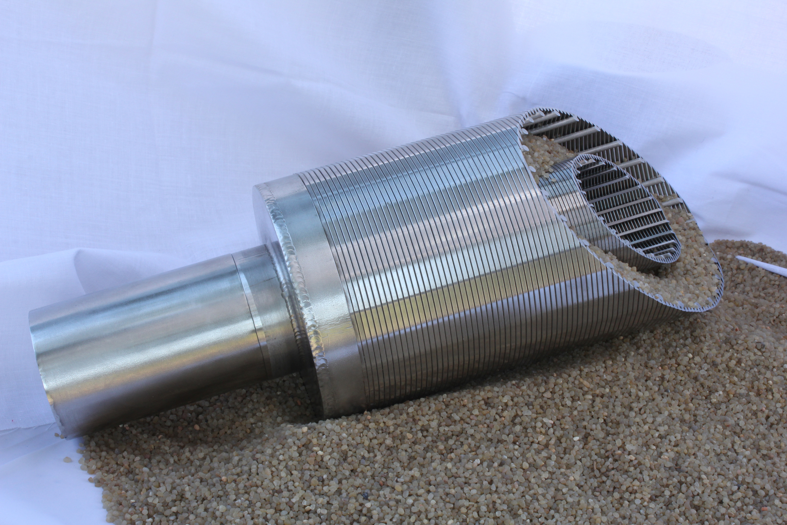
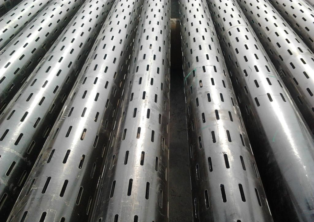
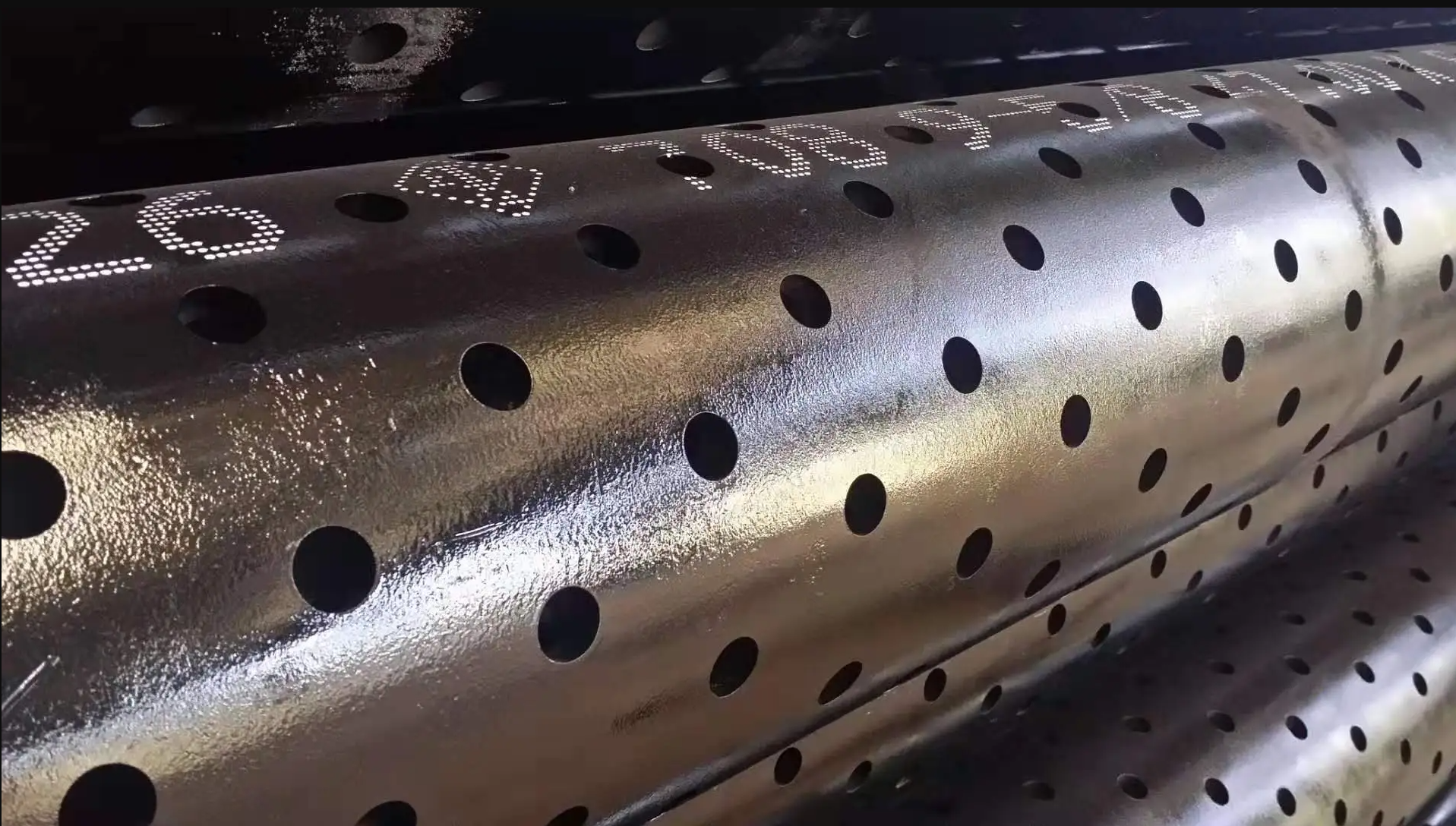
The fundamental brilliance of the Johnson type screen—also known as the wedge wire screen—lies in its geometry. Traditional perforated pipes or slotted liners suffer from a fatal flaw: particles that are slightly smaller than the opening can become wedged halfway through, leading to a permanent reduction in flow and eventual well failure.
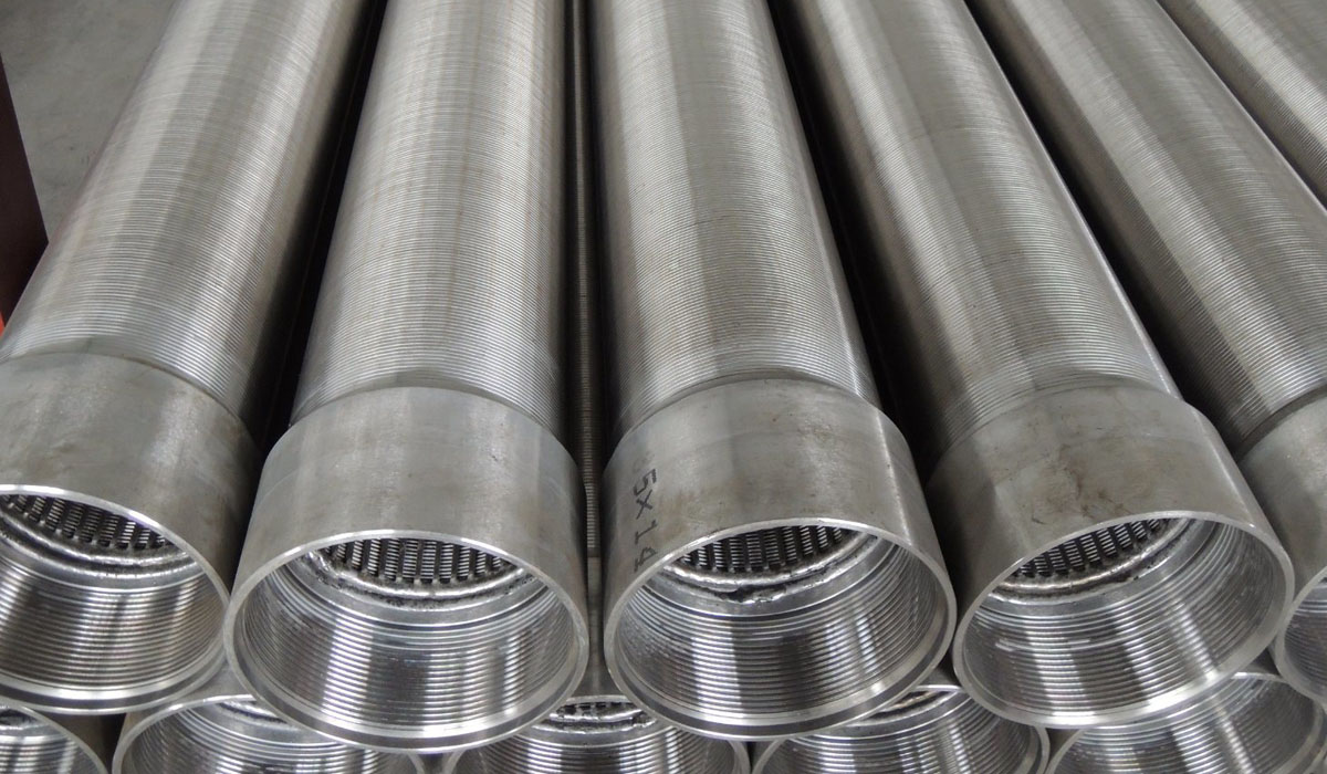
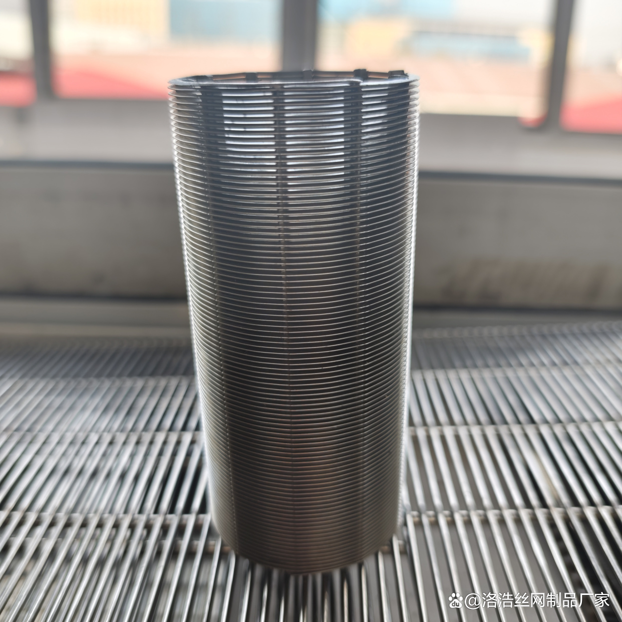
Our engineering team utilizes a continuous V-shaped profile wire, cold-rolled from high-grade stainless steel. By welding this wire onto a circular array of longitudinal support rods, we create an aperture that widens inwardly. This means any particle that passes through the outer “slot” will naturally fall through into the screen interior without getting stuck.
This self-cleaning characteristic is what separates our professional-grade screens from generic alternatives. In a deep-well environment, where chemical encrustation and sand infiltration are constant threats, the “open-area” ratio of our screens remains remarkably consistent over decades.
Material Science: The Stainless Steel Advantage
Choosing the right alloy is not merely a matter of cost; it is a calculation of the corrosive potential of the aquifer. Groundwater is rarely “just water”—it is a complex soup of dissolved CO2, H2S, chlorides, and varying pH levels.
Table 1: Chemical Composition of Stainless Steel Screen Grades
| Grade | Cr (%) | Ni (%) | Mo (%) | C (max %) | N (max %) | P (max %) | S (max %) |
| SS 304 | 18.0–20.0 | 8.0–10.5 | — | 0.08 | — | 0.045 | 0.03 |
| SS 304L | 18.0–20.0 | 8.0–12.0 | — | 0.03 | — | 0.045 | 0.03 |
| SS 316 | 16.0–18.0 | 10.0–14.0 | 2.0–3.0 | 0.08 | — | 0.045 | 0.03 |
| SS 316L | 16.0–18.0 | 10.0–14.0 | 2.0–3.0 | 0.03 | 0.10 | 0.045 | 0.03 |
| SS 904L | 19.0–23.0 | 23.0–28.0 | 4.0–5.0 | 0.02 | — | 0.045 | 0.03 |
For standard irrigation wells, our SS 304 screens provide an excellent balance of cost and longevity. However, for industrial desalination or deep oilfield brine extraction, we recommend SS 316L or even SS 904L. The presence of Molybdenum (Mo) in 316L provides critical resistance to pitting corrosion in high-chloride environments. Furthermore, our “L” (Low Carbon) variants are essential for preventing intergranular corrosion in the heat-affected zones (HAZ) of the resistance welds, ensuring the structural integrity of the screen is not compromised by the manufacturing process itself.
Structural Integrity: Collapse Resistance and Tension
A well screen is subjected to immense hydrostatic pressure and the weight of the casing string above it. The design of the support rods—those vertical pillars inside the screen—is where our technical superiority is most evident. We don’t just use standard rods; we calculate the required moment of inertia for each project based on the planned depth and the expected differential pressure.
Table 2: Technical Specifications & Performance Parameters
| Parameter | Range / Standard | Impact on Well Performance |
| Slot Size (mm) | 0.05 mm – 20.0 mm | Controls sand filtration efficiency |
| Open Area (%) | 15% – 60% | Affects flow velocity and drawdown |
| Support Rod Type | Round, Triangle, Flat | Determines collapse resistance |
| Max Pressure | Up to 10 MPa (Project specific) | Ensures safety at great depths |
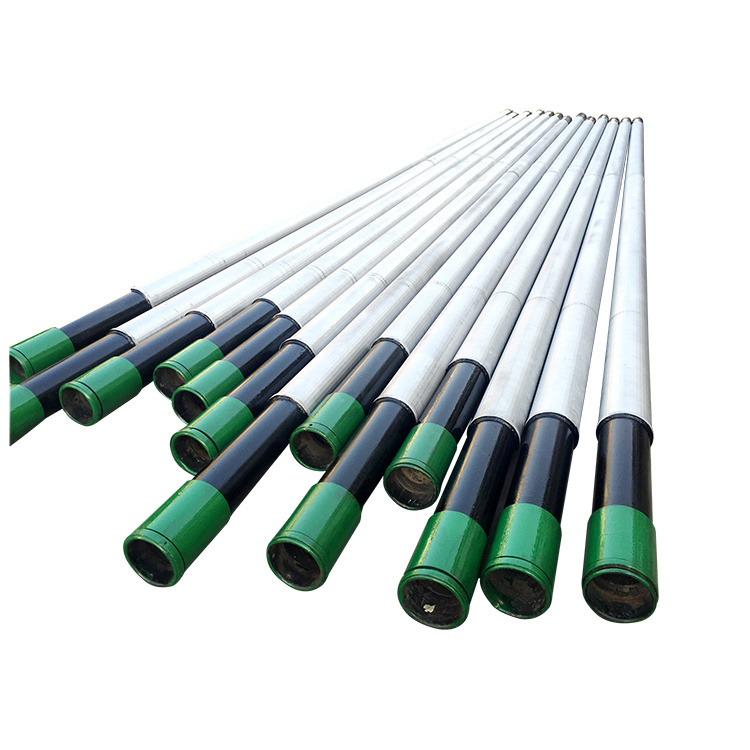
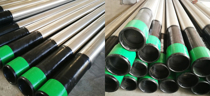
| End Connections | Threaded (NPT/BTC), Flanged, Welded | Affects installation speed and seal |
By optimizing the Open Area, we reduce the “Entrance Velocity” of the water. High-velocity water causes turbulence, which in turn accelerates corrosion and encourages mineral scale buildup. Our screens are designed to keep entrance velocities below 0.03 m/s, which is the industry gold standard for minimizing well maintenance costs.
Precision Manufacturing: The Fusion Point
Every intersection of the V-wire and the support rod in our screens is joined by Resistance Welding. Unlike traditional arc welding, which introduces filler material and excess heat, resistance welding uses electrical current and pressure to fuse the materials at the molecular level. This creates a bond that is actually stronger than the wire itself.
Our CNC-controlled winding machines ensure that the slot width is consistent within a tolerance of ±0.01mm. In an aquifer where the sand grain distribution is finely graded, a “loose” tolerance in the slot size can lead to catastrophic sand pumping, which destroys pump impellers and eventually causes the well to collapse.
Why Our Johnson Type Screens are the Industry Benchmark
Our commitment goes beyond simply selling a product; we provide a geological partnership. When you order from us, our engineers analyze your “Sieve Analysis” data of the formation sand. We don’t just sell you a 0.5mm slot; we calculate the exact slot size required to retain 90% of the formation while allowing the finest 10% to be “developed” out, creating a natural gravel pack around the screen.
Our stainless steel Johnson type wire well screens offer:
- Superior Longevity: A lifespan of 30+ years in aggressive environments.
- Reduced Pumping Costs: Lower drawdown due to high open areas.
- High Strength-to-Weight Ratio: Easier handling during installation without risking collapse.
- Traceability: Every screen is shipped with a full material certificate (MTC) and quality inspection report.
Whether you are rehabilitating an old well or embarking on a massive municipal water project, the filtration interface is the one place where quality cannot be compromised. Our screens represent the pinnacle of wire-wrap technology, ensuring that what comes out of your well is pure, consistent, and sand-free.
To provide a rigorous technical calculation for your well design, we must move beyond generalities and into the mathematics of hydraulic efficiency and soil mechanics. The performance of a Stainless Steel Johnson Type Wire Well Screen is governed by the relationship between the formation’s particle size distribution and the screen’s hydraulic capacity.
Part 1: Determination of Slot Size (Sieve Analysis)
The most critical decision in well design is the slot width. Selecting a slot that is too large leads to “sand pumping,” which destroys pumps; selecting one too small leads to excessive “drawdown” and energy waste.
In a naturally developed well (without an artificial gravel pack), we typically apply the D-percentile rule. We analyze the formation samples and plot a grain size distribution curve.
- Reliable Filtration Rule: For most stable aquifers, the slot size is selected to retain 60% to 70% of the formation ($D_{60}$ or $D_{70}$). The finer 30% to 40% of the material is intended to be drawn through the screen during the “well development” phase, creating a highly permeable natural envelope of coarser pebbles around the screen.
- Formula for Slot Selection:
$$Slot\ Width \approx D_{60} \text{ (of the formation sample)}$$
Part 2: Open Area and Entrance Velocity
The “Open Area” is the percentage of the screen surface that allows water to pass. Unlike perforated pipes, our Johnson type screens can achieve up to 60% open area, which is vital for reducing Entrance Velocity ($V_e$).
The industry standard (to prevent encrustation and corrosion acceleration) is to keep $V_e$ below 0.03 m/s (roughly 0.1 ft/sec).
To calculate the required screen length ($L$) or diameter ($D$) for a target flow rate ($Q$), we use:
Where $A_o$ is the total open area of the screen surface.
If your aquifer has a high concentration of iron or manganese, we recommend an even lower entrance velocity to prevent the pressure drop that triggers mineral precipitation (clogging).
Table 3: Hydraulic Capacity for Standard 6-inch (168mm) Johnson Screen
| Slot Size (mm) | Open Area (%) | Intake Capacity (m3/h/m) at 0.03 m/s | Structural Grade |
| 0.25 | 12.5% | 18.2 | Heavy Duty |
| 0.50 | 22.8% | 33.1 | Standard |
| 0.75 | 31.4% | 45.6 | Standard |
| 1.00 | 38.2% | 55.5 | Standard |
| 2.00 | 55.1% | 80.1 | Light/Medium |
Part 3: Deep Well Collapse Resistance (The Support Rod Factor)
As we go deeper, the hydrostatic pressure and the weight of the “filter pack” (if used) exert massive radial pressure on the screen. While the V-wire provides the filtration, the internal support rods provide the structural skeleton.
Our technical department uses the Lundquist Equation to calculate the critical collapse pressure ($P_c$). By adjusting the shape and frequency of the support rods (e.g., using 3.0 x 5.0 mm “teardrop” rods instead of 2.0 mm round rods), we can increase the collapse strength by up to 400% without significantly reducing the internal diameter.
Why Our Technical Consultation Matters
When you partner with us, you aren’t just buying a commodity. We provide a Project Design Verification report that includes:
- Velocity Profiling: Ensuring the flow is laminar (smooth) rather than turbulent.
- Material Compatibility: Analyzing your water chemistry (pH, TDS, $Cl^-$) to confirm if SS 304L is sufficient or if the project requires the molybdenum-enhanced SS 316L.
- Tension Load Analysis: Calculating the maximum “hang weight” the screen can support during installation in deep bores.
Our screens are manufactured with a continuous-slot design, meaning there are no “dead zones” or interruptions in the flow. This ensures that the entire circumference of the aquifer is being utilized, which maximizes the specific capacity of your well.