Preface
This document is for the engineers, the procurement specialists, and the project managers who need the unvarnished truth about Bearing Pipe Piles.
We’re not just bending steel here. We’re creating the structural sinew that connects monumental human ambition to the indifferent earth. My goal is to bridge the gap between the metallurgist’s lab and the pile driver’s hammer. We’ll dig deep into the why—why a specific grade fails in a certain soil, why a weld seam orientation matters when you’re driving through glacial till, and why sometimes, the cheapest pile per ton is the most expensive pile per year of service life.
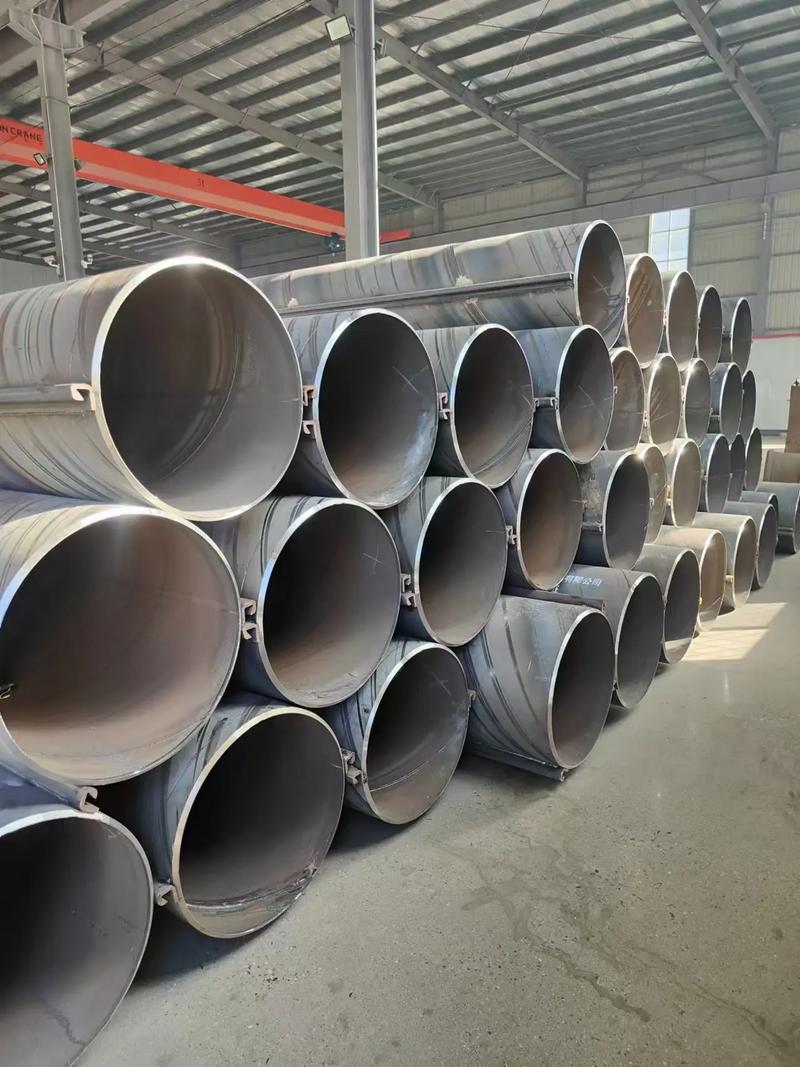
BEARING PIPE PILES
weight per meter (kg/m) · complete specification table
| OD (in) | OD (mm) | 5.6 | 6.4 | 7.1 | 7.9 | 8.7 | 9.5 | 10.3 | 11.1 | 12.7 | 14.3 | 15.9 | 17.5 | 19.1 | 20.6 | 22.2 | 25.4 |
|---|---|---|---|---|---|---|---|---|---|---|---|---|---|---|---|---|---|
| wall (in) → | 7/32 | 1/4 | 9/32 | 5/16 | 11/32 | 3/8 | 13/32 | 7/16 | 1/2 | 9/16 | 5/8 | 11/16 | 3/4 | 13/16 | 7/8 | 1 | |
| 8 5/8 | 219 | 29.48 | 33.57 | 37.11 | 41.14 | 45.13 | 49.10 | ||||||||||
| 10 3/4 | 273 | 36.93 | 42.08 | 46.56 | 51.65 | 56.71 | 61.74 | 68.74 | 71.70 | 81.54 | |||||||
| 12 3/4 | 324 | 43.95 | 50.10 | 55.46 | 61.55 | 67.61 | 73.64 | 79.64 | 85.61 | 97.45 | 109.16 | ||||||
| 14 | 356 | 48.33 | 55.11 | 61.02 | 67.74 | 74.42 | 81.08 | 87.71 | 94.30 | 107.39 | 120.36 | ||||||
| 16 | 406 | 55.35 | 63.13 | 69.91 | 77.63 | 85.32 | 92.98 | 100.01 | 108.20 | 123.30 | 138.27 | 153.11 | |||||
| 18 | 457 | 62.36 | 71.15 | 78.81 | 87.53 | 96.22 | 104.88 | 113.51 | 122.11 | 139.21 | 156.18 | 173.03 | |||||
| 20 | 508 | 69.38 | 79.16 | 87.70 | 97.43 | 107.12 | 116.78 | 126.41 | 136.01 | 155.12 | 174.10 | 192.95 | 211.68 | ||||
| 22 | 559 | 76.39 | 87.18 | 96.59 | 107.32 | 118.02 | 128.68 | 139.32 | 149.92 | 171.03 | 192.01 | 212.87 | 233.60 | 254.20 | |||
| 24 | 610 | 83.41 | 95.20 | 105.49 | 117.22 | 128.92 | 140.59 | 152.22 | 163.83 | 186.94 | 209.93 | 232.79 | 255.52 | 278.13 | 299.21 | ||
| 26 | 660 | 90.43 | 103.22 | 114.38 | 127.12 | 139.82 | 152.49 | 165.12 | 177.73 | 202.85 | 227.84 | 252.70 | 277.41 | 302.06 | 325.02 | 349.38 | |
| 28 | 711 | 97.44 | 111.23 | 123.28 | 137.01 | 150.72 | 164.39 | 178.03 | 191.64 | 218.76 | 245.75 | 272.62 | 299.37 | 325.98 | 350.82 | 377.19 | 429.56 |
| 30 | 762 | 104.46 | 119.25 | 132.17 | 148.91 | 161.61 | 176.29 | 190.93 | 205.54 | 234.67 | 263.67 | 292.54 | 321.29 | 349.91 | 376.63 | 405.00 | 461.38 |
| 32 | 813 | 111.47 | 127.27 | 141.07 | 158.81 | 172.51 | 188.19 | 203.83 | 219.45 | 250.58 | 281.58 | 312.46 | 343.21 | 373.84 | 402.43 | 432.82 | 493.20 |
| 34 | 864 | 118.49 | 135.29 | 149.96 | 166.70 | 183.41 | 200.09 | 216.74 | 233.35 | 266.49 | 299.50 | 332.38 | 365.13 | 397.76 | 428.24 | 460.63 | 525.02 |
| 36 | 914 | 125.50 | 143.30 | 158.86 | 176.60 | 194.31 | 211.99 | 229.64 | 247.26 | 282.40 | 317.41 | 352.30 | 387.06 | 421.69 | 454.05 | 488.44 | 556.84 |
| 38 | 965 | 132.52 | 151.32 | 167.75 | 186.50 | 205.21 | 223.89 | 242.54 | 261.16 | 298.31 | 335.32 | 372.21 | 408.98 | 445.62 | 479.85 | 516.25 | 588.66 |
| 40 | 1016 | 139.53 | 159.34 | 176.64 | 198.39 | 216.11 | 235.79 | 255.45 | 275.07 | 314.22 | 353.24 | 392.13 | 430.90 | 469.55 | 505.66 | 544.06 | 620.48 |
| 42 | 1067 | 146.55 | 167.36 | 185.54 | 206.29 | 227.01 | 247.69 | 268.35 | 288.97 | 330.13 | 371.15 | 412.05 | 452.83 | 493.47 | 531.47 | 571.87 | 652.30 |
| 44 | 1118 | 153.56 | 175.37 | 194.43 | 216.19 | 237.91 | 259.59 | 281.25 | 302.88 | 346.03 | 389.07 | 431.97 | 474.75 | 517.40 | 557.27 | 599.68 | 684.11 |
| 46 | 1168 | 183.39 | 203.33 | 226.08 | 248.80 | 271.50 | 294.16 | 316.78 | 361.94 | 406.98 | 451.89 | 496.67 | 541.33 | 583.08 | 627.49 | 715.93 | |
| 48 | 1219 | 212.22 | 235.98 | 259.70 | 283.40 | 307.06 | 330.69 | 357.85 | 424.89 | 471.81 | 518.59 | 565.25 | 608.88 | 655.30 | 747.75 | ||
| 52 | 1321 | 285.70 | 307.20 | 332.86 | 358.50 | 409.67 | 460.72 | 511.64 | 562.44 | 613.11 | 680.50 | 710.92 | 811.39 | ||||
| 56 | 1422 | 303.30 | 331.00 | 358.67 | 386.31 | 441.49 | 496.55 | 551.48 | 606.28 | 660.96 | 712.11 | 766.54 | 875.03 | ||||
| 60 | 1524 | 351.80 | 381.48 | 414.12 | 473.31 | 532.38 | 591.32 | 650.13 | 708.82 | 763.72 | 823.16 | 938.67 | |||||
| 64 | 1626 | 410.28 | 441.93 | 505.13 | 568.21 | 631.15 | 693.98 | 756.67 | 815.33 | 877.78 | 1002.31 | ||||||
| 68 | 1727 | 469.74 | 536.95 | 604.03 | 670.99 | 737.82 | 804.53 | 866.95 | 933.41 | 1065.95 | |||||||
| 72 | 1829 | 568.77 | 639.86 | 710.83 | 781.67 | 852.38 | 918.56 | 989.03 | 1129.58 | ||||||||
| 78 | 1981 | 693.60 | 770.58 | 847.43 | 924.16 | 995.98 | 1072.46 | 1225.04 | |||||||||
| 100 | 2540 | 898.68 | 1088.58 | 1187.36 | 1279.85 | 1378.37 | 1575.05 | ||||||||||
| 120 | 3048 | 1307.81 | 1426.63 | 1537.91 | 1656.48 | 1893.25 | |||||||||||
ⓘ production note OD 219–3200 mm · wall up to 25.4 mm (1″). For thicker walls / high steel grades (above 25.4mm) please check production feasibility prior to order.
📋 Material grades: Q235–Q500 (Gr.B–X70) · ASTM A252, A533, A333 · EN 10219 · AS 1163, AS1579 · JIS 5525 · API Spec 5L · SY/T5040, SY/T5037
✓ table matches ASTM A252 / EN 10219 weight calculation (density 7.85 t/m³)
bearing pipe piles — technical weight reference (v.2025.03) — compiled for engineers & contractors
1. Foundational Concepts: What We’re Really Dealing With
1.1 Definition & Core Purpose: The Unsung Hero
Let’s cut the academic jargon. A bearing pipe pile? It’s a steel tube you hammer, jack, or drill into the ground until it hits something that won’t move. Its job is brutally simple: take the load of whatever you’re building up top—be it a 50-story condo or a 500-ton bridge girder—and shuttle that weight down through weak surface soils to a competent load-bearing stratum deep below.
We’re solving for two main headaches: bearing capacity failure (think the Leaning Tower of Pasta, but faster) and unacceptable settlement (that sinking feeling when your brand-new warehouse floor dips six inches). In soft clays or loose sands, a concrete spread footing is a recipe for disaster. That’s where we come in. We’re the intervention between the structure and the mud.
1.2 Governing Standards: The Bible and the Law
In the pipe mill, the standard isn’t just a number on a page; it’s the recipe. Deviate from it, and you’re cooking up trouble. We live and die by these specs:
-
ASTM A252 (Grades 1, 2, & 3): This is the undisputed heavyweight champion for pipe piles in North America and much of the world. It’s the benchmark. Grade 1 (30 ksi yield) is for light work. Grade 2 (35 ksi) is your everyday workhorse. Grade 3 (45 ksi) is for when the loads get serious. We’ll talk about why just picking Grade 3 isn’t always smart, though.
-
EN 10219 (S235, S275, S355, S460): The European standard for cold-formed welded sections. S355 (355 MPa yield, roughly 51 ksi) is a beast and is often specified for higher-load applications where you want to save weight.
-
API 5L (Grade B, X42, X52…): This is pipeline steel. We sometimes use it for piles, especially large-diameter, heavy-wall stuff for offshore or river crossings. The chemistry is a bit different—tuned for toughness and weldability—and it often comes with more rigorous testing (like CVN impact tests) which can be a huge bonus in seismic or cold-weather zones.
-
JIS A 5525 (SKK400, SKK490): The Japanese Industrial Standard for steel pipe piles. Common in Asia-Pacific.
A Field Note: Don’t just specify “ASTM A252.” Tell me the Grade. And if you’re driving in -40°C in Northern Alberta, you better be asking for supplementary Charpy V-Notch (CVN) impact testing, even if the base standard doesn’t require it. That’s experience talking.
1.3 Core Characteristics: The Big Picture
Why steel pipe over concrete or H-piles? Here’s the real-world breakdown:
-
Load-Bearing Muscle: High strength-to-weight ratio. You get immense axial and bending capacity without the massive weight of precast concrete. This means cheaper transport and lighter cranes.
-
Drivability: It’s a closed or open-ended tube. It displaces soil, but it’s also tough. It can handle the hammer. It can be driven through dense sands and even soft rock without shattering, unlike concrete.
-
Inspectability: I can go inside a large-diameter pipe pile after driving with a camera or even a person and see the condition. Try that with a concrete pile.
-
Adaptability: Need to add 10 feet because the soil layer dropped? Weld on an extension. Cut one off that’s too high? Torch it. On-site modification is straightforward.
-
Sustainability: When the building’s life is over, I can cut that pile off at the mudline and pull it out. 100% recyclable. No concrete rubble to haul to a landfill.
2. Navigating the Product Maze: Selection & Classification
Choosing the right pile is half art, half science. It’s about matching the mill’s capabilities to the ground conditions and the loading. Here’s how we break it down on the shop floor.
2.1 Classification by Process
How we make the pipe dictates its strengths and weaknesses.
| Manufacturing Process | Typical Diameter Range | Wall Thickness | Key Characteristics | My Take from the Field |
|---|---|---|---|---|
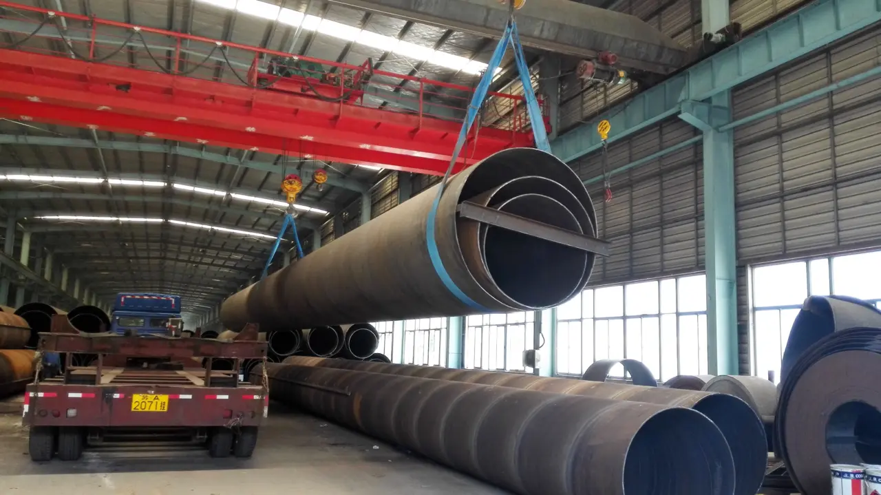
| Spiral Submerged Arc Welded (SAWH) | 16″ (406mm) to 120″ (3000mm)+ | 0.188″ (5mm) to 1″ (25mm)+ | Continuous spiral seam. Highly automated. Excellent uniformity. The weld seam runs around the pipe, which can be beneficial for resisting hoop stresses during driving. | The King of Big Diameters. For port projects, large-diameter caissons, this is usually our go-to. The continuous weld means less chance of a weak point along the longitudinal axis compared to a single long seam. |
| Longitudinal Submerged Arc Welded (LSAW) | 20″ (508mm) to 60″ (1500mm) | Up to 2″ (50mm) or more | Formed from a single steel plate (JCOE or UOE process) with one or two straight seams. Excellent dimensional control, especially for thick walls. | The Precision Load-Bearer. When you need a heavy wall and tight tolerances for a press-fit connection or a specific flange fit-up, LSAW is your friend. More expensive, but for high-stress, heavy-load applications, it’s worth it. |
| Electric Resistance Welded (ERW) | 4″ (100mm) to 24″ (600mm) | Up to 0.75″ (19mm) | High-frequency current welds the seam. Very fast, very cost-effective for smaller diameters. The weld zone is narrow and heat-affected. | The Workhorse for Buildings. For most building foundations in the 12-24 inch range, ERW is perfectly adequate. However, you must trust the mill’s non-destructive testing (NDT). A bad ERW seam can unzip under the hammer. |
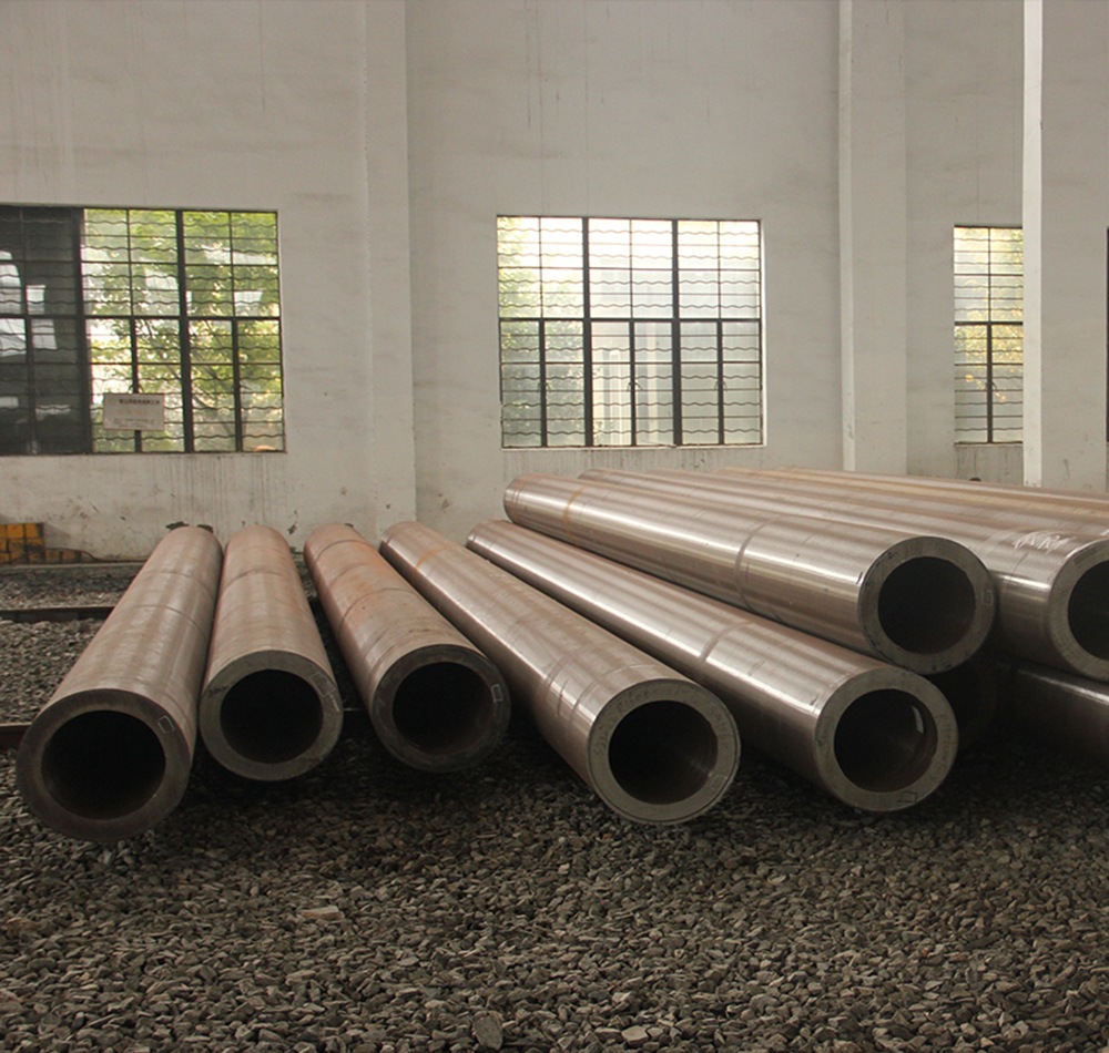
| Seamless | 2″ (50mm) to 26″ (660mm) | Variable, limited by mill capacity | A solid billet of steel is pierced and rolled. No weld seam. | The Specialist. Expensive. We use it when we absolutely, positively cannot have a weld seam—maybe for a very high-pressure grout system inside, or in a highly corrosive environment where we worry about preferential weld corrosion. Overkill for 99% of jobs. |
2.2 Classification by End Use & Geometry
-
Open-Ended Pipe Piles: You drive them, and a soil plug forms inside. The load is carried by skin friction on the outside and end bearing on the steel annulus and the internal soil plug. Great for dense sands and gravels where the plug provides resistance.
-
Closed-Ended Pipe Piles: A steel plate (or cast steel shoe) is welded over the end. You get a displacement pile—it pushes soil out of the way. This increases soil densification (good for friction) but requires more driving force. Essential for soft clays where you need to maximize friction and prevent soil from entering.
A Story: We had a job on the Houston Ship Channel. Soft clays overlying a dense sand layer at 80 feet. Contractor used open-ended piles. They drove like butter until they hit the sand, then refused. The problem? The internal soil plug had locked up, and they were trying to drive a solid steel bar 80 feet long. We switched to a heavier wall with a thinner internal coating, and added a slightly tapered driving shoe to break the plug’s adhesion. Night and day.
2.3 Classification by Armor: The Corrosion Fight
This is where “cheap” gets expensive. You must match the coating to the environment.
| Environment | Corrosion Rate (per year, first 10 yrs) | Recommended Coating Type | Notes |
|---|---|---|---|
| Dry Inland Soils (Sand) | Negligible (< 0.001 in) | None (Bare) or Mill varnish | Honestly, bare steel is fine for most structures’ design life in these conditions. The corrosion is so slow it’s not a structural factor. |
| Disturbed Inland Soils (Clay/Loam) | 0.001 – 0.003 in | Fusion Bonded Epoxy (FBE) or Coal Tar Epoxy | FBE is clean, tough, and handles some handling damage. Coal tar is cheap but messy. Environmental regs are killing coal tar use. |
| Marine Splash / Tidal Zone | 0.005 – 0.020 in (severe) | Heavy-Duty FBE, or FBE + Polymer Wrap, or Monel Sheathing | The War Zone. The constant wet-dry cycle and oxygen accelerate corrosion like crazy. A 100-mil coating system is a must. For really critical stuff, we weld on a monel metal sheath at the splash zone. It’s expensive, but it’s 100-year protection. |
| Marine Immersion | 0.003 – 0.007 in | FBE or Coal Tar Enamel with fiberglass wrap | Lower oxygen, but still corrosive. Cathodic protection (sacrificial anodes) is often used in addition to coating. |
| Chemical / Industrial Fill | Variable | 3-Layer Polyethylene (3LPE) | The gold standard for pipelines, and great for piles in aggressive chemical fills. Provides mechanical protection and a chemical barrier. |
My Advice: Never, ever use galvanizing for driven piles. The zinc will scrape off on the first rock it hits. You’ve just wasted your money. Coatings for driven piles must be tough, flexible, and damage-tolerant. FBE is the current king for a reason.
3. Core Specifications & Technical Data: The Nuts and Bolts
Alright, let’s get into the numbers. This is the stuff you put in your tender docs. But I’m going to add the “why” behind each number.
3.1 Dimensional Scope (What We Can Roll)
-
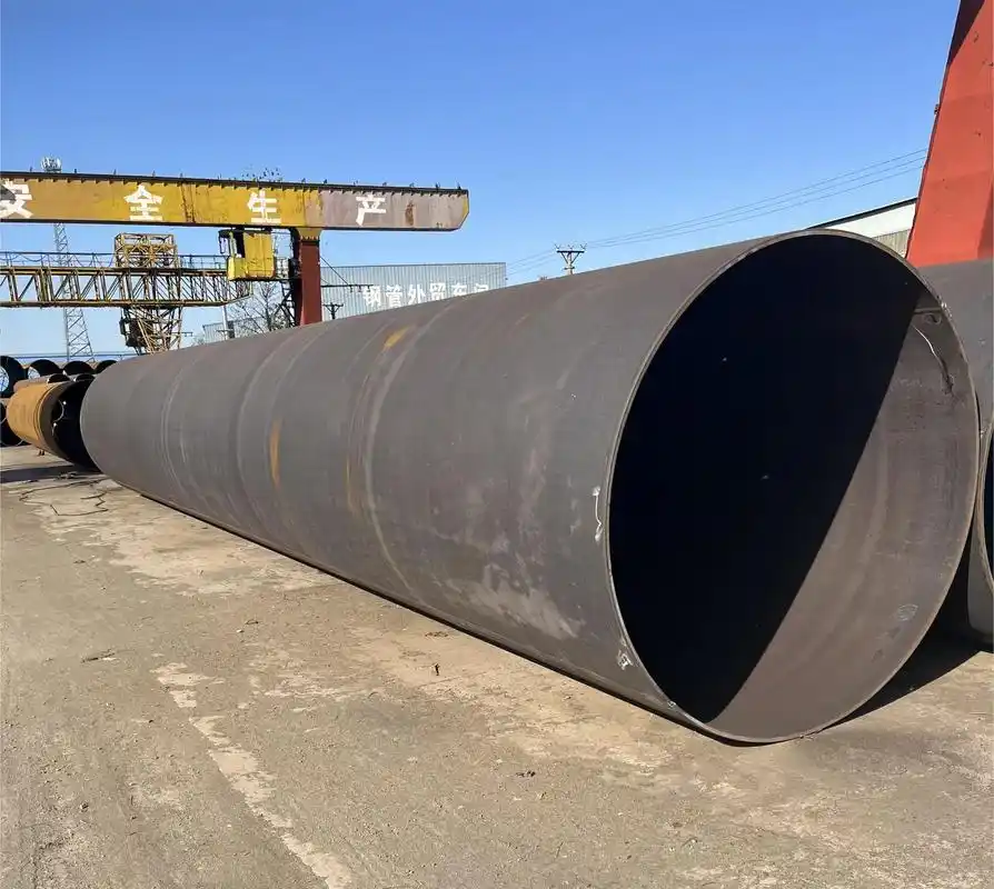
Outer Diameter (OD): We routinely run from 219mm (8 inches) up to 2020mm (80 inches). For bespoke, large-diameter monopile foundations (offshore wind), we’re talking 4 meters+ in diameter. That’s a different beast entirely.
-
Wall Thickness (WT): From 6.4mm (1/4″) for light bracing piles, up to 50mm (2″) for heavy-load, large-diameter rock sockets. The sweet spot for most building work is 10mm to 20mm.
-
Lengths: Standard mill lengths are usually 12m (40ft) for shipping efficiency. We weld them end-to-end in the yard or on-site to reach required depths of 30m, 60m, or more. This field splice is critical—I’ll get to that.
- Steel Grades (The Usual Suspects):
-
Q355B / ASTM A252 Grade 3: The workhorse. 355 MPa (45 ksi) yield. Good toughness, good weldability. 80% of what we sell.
-
Q460C / API 5L X65: High-strength. Used when you need to reduce wall thickness to drive through very dense material, or to handle huge bending moments. Harder to weld, more prone to hydrogen cracking if you’re not careful with preheat.
-
S355G10+M: Offshore magic. This is thermomechanically rolled steel with guaranteed through-thickness toughness and very low carbon equivalents (CEV). It’s designed to be welded without preheat in thick sections, which is a godsend on a rolling barge.
-
3.2 Key Technical Parameters (The Devil’s in the Details)
Mechanical Properties (Minimum Spec)
| Grade | Yield Strength (MPa/ksi) | Tensile Strength (MPa/ksi) | Elongation (%) | Typical Application |
|---|---|---|---|---|
| ASTM A252 Gr 2 | 240 / 35 | 414 / 60 | 22 | Light industrial, secondary piling |
| ASTM A252 Gr 3 | 310 / 45 | 455 / 66 | 20 | Standard for most buildings & bridges |
| EN 10219 S355J2H | 355 / 51 | 470-630 / 68-91 | 20 | European spec, higher strength, good toughness |
| API 5L X60 | 415 / 60 | 520 / 75 | 18 | Pipeline steel, used for higher strength needs |
The “Why”: Don’t just look at yield. Look at the yield-to-tensile ratio. If it’s too high (e.g., >0.90), the steel has very little “plastic” reserve capacity before it snaps. For seismic areas, you want a lower ratio so the pile can bend and deform without fracturing. A252 Gr3 is usually pretty safe. Some ultra-high-strength grades can be brittle.
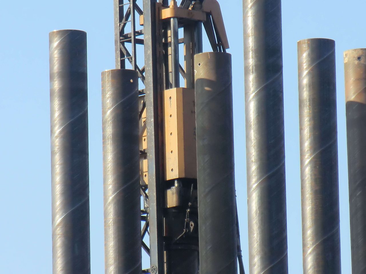
Driving Stresses: The Unseen Hammer
The rule of thumb: the driving stress (the hammer impact) should be kept below 0.9 * (Specified Minimum Yield Strength). For a Gr3 pile (45 ksi yield), that’s about 40.5 ksi. If your hammer is consistently sending 50 ksi stress waves down the pile, you’re going to yield the steel, maybe buckle it, or damage the welds. This is why we use Pile Driving Analyzers (PDA) . It’s not just for capacity; it’s to watch the driving stress in real-time to make sure we’re not destroying the pile we’re trying to install.
Dimensional Tolerances (Why “Close Enough” Isn’t)
| Parameter | ASTM A252 Tolerance | EN 10219 Tolerance | Why It Matters |
|---|---|---|---|
| Outside Diameter | ±1% of specified OD | ±1% (but tighter on critical sizes) | For splicing. If one pipe is +1% and the next is -1%, you have a 2% mismatch. Makes fit-up a nightmare. |
| Wall Thickness | -12.5% (under-thickness not allowed to exceed) | -10% (for thicknesses < 16mm) | This is structural. A thinner wall reduces load capacity. We always order heavy. The minus tolerance is the mill’s allowance, but we target the nominal. |
| Straightness | 0.2% of length | 0.15% of length | A crooked pile drives crooked. It can hit the hammer leads wrong, damage the pile, or end up in the wrong location. |
| Squareness of Ends | 1/16″ per inch of diameter (max 3/8″) | Pretty tight | For butt welding. A non-square end creates a stress concentration at the weld root. |
3.3 Weight Tables (The Cost Calculator)
You need this for freight, craneage, and steel cost. Here’s a sample for common sizes. Remember, this is theoretical. Actual weight can vary by +/- 5% due to mill tolerances.
| Outer Diameter (mm) | Wall Thickness (mm) | Weight per Meter (kg/m) | Cross-Sectional Area (cm²) |
|---|---|---|---|
| 323.9 (12.75″) | 9.5 (3/8″) | 73.5 | 93.7 |
| 12.7 (1/2″) | 97.1 | 123.7 | |
| 406.4 (16″) | 9.5 (3/8″) | 92.7 | 118.1 |
| 12.7 (1/2″) | 122.8 | 156.5 | |
| 16.0 (5/8″) | 153.7 | 195.9 | |
| 508.0 (20″) | 9.5 (3/8″) | 116.3 | 148.2 |
| 12.7 (1/2″) | 154.6 | 197.0 | |
| 16.0 (5/8″) | 194.1 | 247.4 | |
| 610.0 (24″) | 12.7 (1/2″) | 186.5 | 237.6 |
| 16.0 (5/8″) | 234.2 | 298.4 | |
| 20.0 (3/4″) | 291.5 | 371.5 |
4. Engineering Value: Why We Choose Steel Pipe
We’ve covered the “what.” Now for the “why it matters.”
4.1 Structural Muscle: The Axial and Flexural Champ
Let’s put a number on it. The nominal axial compressive capacity (Pn) of a pipe pile, before slenderness effects, is roughly:
Pn = Fy * Ag
Where:
- Fy = Yield strength of steel
- Ag = Gross cross-sectional area of steel
Take a 508mm x 12.7mm pile (20″ x 0.5″) in A252 Gr3 (Fy = 310 MPa, or 31,600 tonnes/m²). Ag from the table is 0.0197 m².
Pn = 31,600 t/m² * 0.0197 m² = 622 tonnes
That’s over 600 tons of axial capacity from a single piece of steel, before you even count the soil plug or skin friction! A comparable concrete-filled pipe? The steel alone gives it massive ductility and bending resistance (moment capacity) that a plain concrete pile can’t touch. In seismic zones, that moment capacity is everything. It lets the building rock and sway while the piles flex without snapping.
4.2 Construction Speed: Time is Money
I’ve been on sites where they’re driving 50 pipes a day. Try that with cast-in-place concrete piles. You drill the hole, put the rebar cage in, pour the concrete, wait for it to cure, and test it. That’s days per pile, not hours. With steel pipe:
-
Delivery: Truck shows up with the pile.
-
Lifting: Crane picks it.
-
Driving: Hammer drives it in an hour or less.
-
Splicing: Need more length? Weld on another section in under an hour with a qualified crew.
-
Immediate Loading: You can put a cap on it and start building the next day. No curing time.
On a project like a new Walmart distribution center with 2,000 piles, saving two days per pile is years of schedule compression.
4.3 Durability & Lifecycle Cost: The Long Game
Corrosion is the enemy. But we can manage it.
-
General Corrosion: In most soils, as mentioned, it’s slow. You can even add “sacrificial steel” to your design (increase wall thickness by 1/16″) to account for 50 years of corrosion and not even need a coating.
-
Localized Corrosion: Pitting, crevice corrosion at the mudline. This is where coatings and cathodic protection come in.
A Field Example: We inspected a bridge in Florida built in the 1960s using uncoated steel pipe piles in a salt marsh. The piles above the mudline were rusted paper-thin in places. Below the mudline? They looked almost brand new. The lack of oxygen in the saturated soil stopped the corrosion. This is why we focus so much on the splash zone—that’s the killer. A good epoxy at the top 5 meters saves the whole pile.
4.4 Economics & Sustainability
Steel is the most recycled material on the planet. At the end of a building’s life, we can pull those piles (if not grouted in), melt them down, and make new steel for a fraction of the energy of virgin ore. Concrete? It’s downcycled into road base or ends up in a hole. The carbon footprint argument is shifting, and steel pipe piles are looking greener every year, especially with the rise of electric-arc furnace (EAF) steel made from scrap.
5. Where We Use Them: A Project Engineer’s Tour
This isn’t a theoretical list. These are places I’ve personally seen our piles driven.
-
Port of Long Beach, California: Retrofitting old wharves. We supplied massive 36-inch diameter, 1-inch thick LSAW piles with heavy-duty FBE coating. They were driven through the old timber cribbing into the bedrock below. The driving was brutal—they had to punch through old concrete and rock. The thick wall was essential to prevent the pile end from crumpling.
-
A High-Rise in Dubai’s Marina: Soft desert sands over deep bedrock. They used long, closed-ended piles driven to refusal. The issue was negative skin friction as the surrounding sand settled over time. The steel piles had to be designed with a slip-coating (bitumen) in the upper section to prevent the settling soil from dragging the pile down (“downdrag”).
-
Wind Farm in the North Sea: The monopiles are the ultimate pipe pile. 8 meters in diameter, 80 meters long, weighing 1,500 tons. They’re driven 30 meters into the seabed. The manufacturing tolerances are insane—the flange at the top, where the tower bolts on, must be perfectly flat within a millimeter. That’s the high end of our world.
-
A Bridge over the Mississippi River: They used battered piles (driven at an angle) to resist the huge lateral forces from river currents and barge impacts. The pipe had to be strong enough to handle the bending from the driving hammer while being hammered at an angle. Not easy.
-
A Power Plant in Indonesia: Coastal site, very soft clays. They used very long, large-diameter, relatively thin-wall piles. The challenge was driving them without buckling. We had to specify a thicker wall at the top (the “driving head”) to take the hammer impact, and a thinner wall down below where the stresses were lower. That’s a “step-taper” or variable wall pile.
6. The Crucible: Manufacturing & Quality Control
This is where the rubber meets the road. How do we make sure a pile doesn’t fail?
6.1 The Journey from Coil to Completion
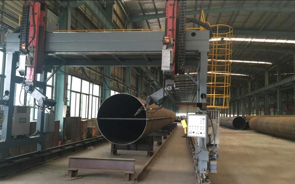
For a spiral weld pile (our most common product), it looks like this:
-
Coil Unloading & Leveling: The steel coil arrives with its mill certs. We check the width, thickness, and surface condition. This steel is our baby.
-
Edge Milling: The edges of the strip are sheared to create a precise, clean, beveled edge for welding. This is critical for weld penetration.
-
Forming & Spiral Welding: The strip is fed into a machine that angles it and forms it into a continuous spiral. As it forms, the first welding head (inside) welds the seam. A few feet later, the second head (outside) welds it again. It’s a continuous, beautiful process. The weld pool is protected by a blanket of granular flux (Submerged Arc).
-
Ultrasonic Testing (UT): Immediately after the outside weld, an ultrasonic probe scans the weld seam for lack of fusion, slag inclusions, or cracks. If it finds a flaw, it marks the spot for repair or cut-out.
-
Cut-Off & Beveling: The pipe is cut to the specified length, and the ends are machined with a bevel for field welding.
-
Hydrostatic Testing: The pipe is filled with water and pressurized to a specified pressure (usually calculated based on the pipe body yield). This checks the integrity of the entire pipe, not just the weld. It weeps? It’s scrap.
-
Visual & Dimensional Inspection: We check straightness, diameter, roundness (less than 1% ovality is the goal), and bevel angle. A crooked pipe is a bad pipe.
-
Coating: If required, the pipe is blast-cleaned to near-white metal (Sa 2.5) and coated.
-
End-User Inspection: The client’s inspector is often on-site for the final UT and visual check. This is our final handshake.
6.2 The Quality Net: Catching the Bad Ones
| Quality Check Point | Method | What We’re Looking For | My Standard |
|---|---|---|---|
| Raw Material | Mill Cert Review + In-house tensile/bend tests | Chemistry (C, Mn, P, S, CEV) and Strength. | If the CEV (Carbon Equivalent) is too high (>0.45 for thick-wall), I flag it. It means the field welds will be harder and require preheat. We talk to the client. |
| Weld Seam | 100% Automated Ultrasonic Testing (AUT) | Lack of fusion, slag, cracks. | This is the primary defense. We calibrate it daily on test blocks with known flaws. |
| Weld Seam | Radiographic Testing (RT) | Spot-check or 100% for critical jobs. | X-ray gives you a picture. It’s great for verifying complex geometries. We do this for offshore work. |
| Weld Cap & Toe | Magnetic Particle Inspection (MT) | Surface cracks in the weld and heat-affected zone. | Especially important after hydrotest. Cracks can open up under pressure. We check the first and last few feet of every pipe for this. |
| Pipe Body | 100% Ultrasonic (Lamb waves) | Laminations or inclusions in the plate itself. | Rare, but it happens. A lamination parallel to the surface can split under the hammer. |
| Coating | Holiday Detector (Spark Test) | Pinholes in the coating. | A 5,000-volt spark jumping through a pinhole finds it instantly. Every inch of coated pipe gets this. |
7. Services & Support: Beyond the Mill Gate
We don’t just throw pipe on a truck and forget you. Here’s what we actually do.
7.1 Customization: The Tailor-Made Pile
-
Driving Shoes: We cast and weld custom shoes. Tapered points for hard driving. Flat plates for end-bearing on rock. We even did one with a cutting edge made of hardened steel for driving through gravel with boulders.
-
Connections: We machine flanges and weld them on. We also make “mechanical splicers”—sleeves that let you stab one pile into another and lock it with pins or grout, for when you can’t weld (e.g., environmentally sensitive areas, underwater). We just finished a job in a river where welding fumes were prohibited. We used a mechanical swaged connection.
-
Drain Holes & Grout Holes: We cut precisely located holes for dewatering the pile during driving, or for tremie grouting after installation.
7.2 The Field Engineer: My Role
When a problem pops up on site, I get the call. Maybe the piles are bouncing (refusal) too soon. Maybe a weld cracked during driving. My job is to look at the driving logs, the PDA data, the soil borings, and the pile material certs, and figure out what’s wrong.
A Recent Puzzle: A job in Texas. 24-inch piles, driving fine for the first 50 feet, then suddenly refusing at 55 feet. PDA showed huge stresses. The soil log showed soft clay then stiff clay. It didn’t make sense. I drove to the site and watched them pull a pile. The inside was packed with clay. The plug had locked up solid. The solution? We cut a 12-inch diameter hole in the side of the pile, about 10 feet up from the tip, before driving the next one. This allowed water and soil to jet out the side as it was driven, preventing the plug from forming. Drove like butter to 80 feet.
7.3 The Warranty: What We Stand Behind
We guarantee the pipe meets the standard—material, dimensions, weld integrity. We don’t guarantee it won’t bend if you hit a boulder at 200 blows per foot. That’s on the installation. But if a weld seam pops during driving, and the PDA data shows the stress was within the acceptable range? We’ll replace it, no questions asked. We’ve got skin in this game.
8. Identification, Packaging & Logistics
8.1 Marking: The Pipe’s ID Card
Every pipe gets stenciled or stamped with:
- Our Brand & Mill Location
-
Specification & Grade: (e.g., ASTM A252 GR3)
-
Heat Number: The code linking it back to the exact ladle of steel it came from.
-
Size & Wall: (e.g., 24″ x 0.500″)
-
Length: (e.g., L=40′)
-
A Unique Serial Number: For full traceability.
This isn’t just bureaucracy. When that pipe is in the ground, and there’s an issue 20 years from now, that heat number lets us go back and check the original mill records to see if there was a chemistry anomaly.
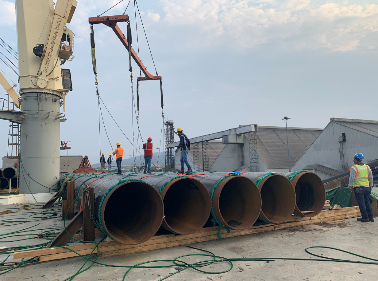
8.2 Packaging: Getting It There Safe
-
Bundling: We band pipes together with steel straps, with wooden dunnage between layers to prevent crushing and allow lifting slings to pass underneath.
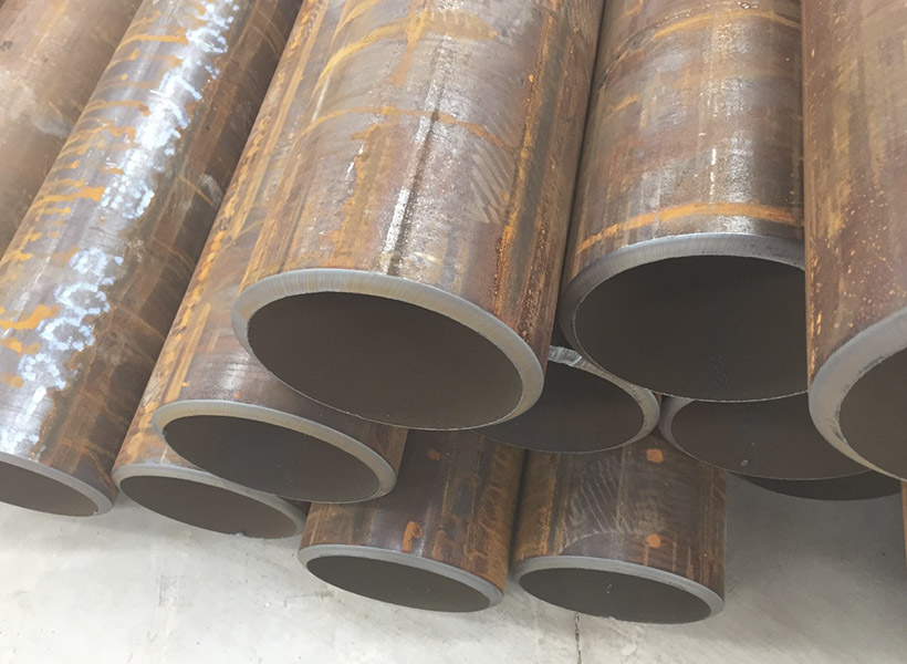
-
End Protection: We install heavy-duty plastic or steel end protectors. A damaged bevel means a bad field weld. It’s cheap insurance.
-
Export Packing: For sea shipments, we use coated straps, add desiccant packs, and sometimes wrap the whole bundle in shrink-wrap for weather protection. We follow the client’s specific ISPM 15 (wood packaging) standards for international shipping.
My advice? Respect the soil. Know your loads. Choose your steel wisely. And never, ever underestimate the importance of a good weld. When you get all that right, you can build something that lasts not just for your lifetime, but for generations.
If you have a project, call me. We’ll talk about the dirt, the loads, and the budget. We’ll figure out the right pile together. Because in the end, it’s not about selling steel; it’s about building something that stands.
The use of pipe piles in foundation construction has been a popular choice for many years. Pipe piles are used to transfer the load of a structure to a deeper, more stable layer of soil or rock.
Benefits of Pipe Trusses The use of pipe trusses in construction offers several notable advantages: Strength and Load-bearing Capacity: Pipe trusses are renowned for their high strength-to-weight ratio. The interconnected pipes distribute loads evenly, resulting in a sturdy and reliable structure. This allows for the construction of large spans without the need for excessive support columns or beams.
The standard for fluid-conveying seamless pipes depends on the country or region you are in, as well as the specific application. However, some widely used international standards for fluid-conveying seamless pipes are: ASTM A106: This is a standard specification for seamless carbon steel pipes for high-temperature service in the United States. It is commonly used in power plants, refineries, and other industrial applications where high temperatures and pressures are present. It covers pipes in grades A, B, and C, with varying mechanical properties depending on the grade. API 5L: This is a standard specification for line pipes used in the oil and gas industry. It covers seamless and welded steel pipes for pipeline transportation systems, including pipes for conveying gas, water, and oil. API 5L pipes are available in various grades, such as X42, X52, X60, and X65, depending on the material properties and application requirements. ASTM A53: This is a standard specification for seamless and welded black and hot-dipped galvanized steel pipes used in various industries, including fluid-conveying applications. It covers pipes in two grades, A and B, with different mechanical properties and intended uses. DIN 2448 / EN 10216: These are European standards for seamless steel pipes used in fluid-conveying applications, including water, gas, and other fluids. Read more
Fluid-conveying seamless pipes are designed to resist various types of corrosion depending on the material used and the specific application. Some of the most common types of corrosion that these pipes are designed to resist include: Uniform corrosion: This is the most common type of corrosion, where the entire surface of the pipe corrodes uniformly. To resist this type of corrosion, pipes are often made of corrosion-resistant materials, such as stainless steel or lined with protective coatings. Galvanic corrosion: This occurs when two dissimilar metals are in contact with each other in the presence of an electrolyte, leading to the corrosion of the more active metal. To prevent galvanic corrosion, pipes can be made of similar metals, or they can be isolated from each other using insulating materials or coatings. Pitting corrosion: Pitting is a localized form of corrosion that occurs when small areas on the pipe's surface become more susceptible to attack, leading to the formation of small pits. This type of corrosion can be prevented by using materials with high pitting resistance, such as stainless steel alloys with added molybdenum, or by applying protective coatings. Crevice corrosion: Crevice corrosion occurs in narrow spaces or gaps between two surfaces, such Read more

Wedge wire screens, also known as profile wire screens, are commonly used in various industries for their superior screening capabilities. They are constructed from triangular-shaped wire,
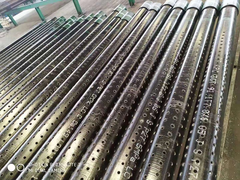
2 7/8in J55 K55 Perforated Well Casing Pipe is one of mainly products of we abter steel, they can be used for water, oil, gas well drilling fields. The thicknesss can be supplied from 5.51-11.18mm based on client's well depth and required mechanical properties. Normally they are provided with thread connection, like NUE or EUE, which will be easier to installed at site. The length of 3-12m perforated casing pipes are available for client's different drilling rigs height. The hole diameter and open area on the surface are also customized. The popular hole diameters are 9mm, 12mm, 15mm, 16mm, 19mm, etc.
