The structure will be:
-
- Introduction:defining pipe bends
- The Engineering Imperative: Why Pipe Bends? Detailed functional explanation (flow dynamics, stress management, piggability).
- Comprehensive Material Portfolio: A Grade-by-Grade Deep Dive: Extensive analysis of the specific carbon steel grades offered, including chemical and mechanical property tables for the general, high-yield, and low-temperature series. This section will be critical for technical depth.
- Sub-section A: General Service (A234 WPB)
- Sub-section B: High-Yield Pipeline Service (A860 / MSS-SP-75 / WPHY Series)
- Sub-section C: Low-Temperature Service (A420 WPL3 & WPL6)
- Mastering the Geometry: Types and Manufacturing Technologies: Detailed breakdown of the bend types, focusing heavily on Hot Induction Bending as the core technology, distinguishing between 3D, 5D, Piggable, Miter, U, and J Bends.
- Technical Parameters and Manufacturing Capabilities (Tables): Necessary tables covering dimensional ranges (OD, WT, Radius), typical standards applied, and production tolerances.
- Quality Assurance and Certification: Discussion of NDE (NDT), testing (Hydrostatic, Impact), and adherence to codes (ASME B31.X).
- Applications Across Critical Industries: Sector-specific uses (Oil & Gas, Power Generation, Petrochemical).
- Conclusion: Summarizing the value proposition.
The Backbone of Industry: Precision Engineered Carbon Steel Pipe Bends
Introduction: Forging the Path for Fluid Transport
In the intricate landscape of global energy infrastructure—from transcontinental oil and gas pipelines to high-pressure chemical processing facilities—the ability to safely, efficiently, and reliably transport media is paramount. While straight pipes define the length of the journey, it is the Pipe Bend that dictates its successful path, enabling crucial changes in direction, accommodating thermal expansion, and facilitating essential maintenance procedures.
A Carbon Steel Pipe Bend is far more than a simple curved section of metal; it is a highly engineered component subjected to immense internal pressure, external stresses, and temperature variations. Its design and manufacturing quality directly impact the integrity, longevity, and operational safety of the entire pipeline system.
Our company stands at the forefront of this critical field, specializing in the precision manufacture of a comprehensive range of Carbon Steel Pipe Bends. Leveraging decades of experience and state-of-the-art Hot Induction Bending (HIB) technology, we provide solutions that adhere to the most rigorous international standards, including ASTM, ASME, MSS-SP-75, and project-specific requirements. Our product portfolio is distinguished by its breadth, encompassing standard service materials like ASTM A234 WPB, high-yield line pipe grades up to WPHY 70, and specialized low-temperature services like A420 WPL6.
This document serves as a definitive guide to our manufacturing capabilities, material excellence, and commitment to delivering the highest quality pipe bends, solidifying our position as the partner of choice for mission-critical piping applications worldwide.
I. The Engineering Imperative: Why Precision Pipe Bends?
To fully appreciate the technical significance of a pipe bend, one must understand its function within the fluid dynamic and mechanical stress environment of a pipeline. While a standard elbow (typically radius) provides an abrupt change in direction suitable for tight spaces, a pipe bend is deliberately designed with a much larger centerline radius (, , and higher) to address fundamental engineering challenges.
1.1 Optimizing Flow Dynamics and Minimizing Pressure Drop
The primary advantage of a Long Radius Bend is its direct impact on fluid mechanics. When fluid changes direction, turbulence is generated, leading to energy dissipation and a measurable pressure drop. A tighter bend (like an elbow) causes a significant hydraulic resistance.
Pipe Bends with radii of (three times the nominal diameter), , or even greater, facilitate a smoother, more laminar transition of the fluid stream. This minimizes eddy current formation, resulting in:
- Reduced Pumping Energy: Lower resistance translates directly into reduced power consumption for pumps and compressors.
- Mitigated Erosion-Corrosion: High-velocity changes in direction increase the risk of wall thinning due to erosion, particularly with multi-phase flow or slurries. The gentle sweep of a large radius bend drastically reduces the impingement angle, extending the operational life of the pipework.
1.2 The Piggability Requirement
In long-distance pipelines, Piggability—the ability to pass an inspection, cleaning, or maintenance tool (Pig) through the line—is non-negotiable. Traditional tight-radius elbows often snag or halt these critical tools.
Our Piggable Bends are designed specifically to ensure the smooth passage of intelligent and utility pigs. This requires:
- Consistent Ovality Control: Maintaining the circular cross-section within tight tolerances throughout the bending arc.
- Minimum Radius Specification: Adhering to the project’s minimum specified bend radius (often or for mainline applications) to prevent jamming.
- Smooth Internal Surface Finish: Minimizing defects and steps that could impede the pig’s progress.
1.3 Stress Management and Thermal Flexibility
Pipelines are subject to significant thermal expansion and contraction due to temperature fluctuations, as well as seismic and ground movement stresses. The inherent flexibility of a large-radius bend acts as a stress absorption mechanism. Unlike rigid connections, the bend can elastically deform to absorb longitudinal stresses, preventing catastrophic failure at joints or anchors. This makes the U Bend and J Bend configurations particularly vital in boiler piping and heat exchanger systems designed to manage extreme thermal cycles.
II. Comprehensive Material Portfolio: A Grade-by-Grade Deep Dive
Our manufacturing expertise is defined by our ability to process and certify an extensive range of carbon steel grades, tailored for specific pressure, temperature, and yield strength requirements. We categorize our offerings into three critical areas: General Service, High-Yield Pipeline Service, and Low-Temperature Service.
2.1 General Service and Entry-Level Specifications
The cornerstone of carbon steel pipe fittings globally is the ASTM/ASME A234 standard.
ASTM/ASME A234 WPB Pipe Bend
- Standard: Standard Specification for Piping Fittings of Wrought Carbon Steel and Alloy Steel for Moderate and High Temperature Service.
- Designation: WPB stands for Weldable Pipe Grade B.
- Application: Widely used in general industrial, power generation, and petrochemical facilities for moderate pressure and temperature applications where cost-efficiency and standard strength are required.
- Key Property: Excellent weldability and good ductility.
| Chemical Requirements (A234 WPB) | Element | Maximum Percent (%) |
| Carbon | C | 0.30 |
| Manganese | Mn | 0.29 – 1.06 |
| Silicon | Si | 0.10 – 0.35 |
| Sulfur | S | 0.050 |
| Phosphorus | P | 0.050 |
2.2 High-Yield Pipeline Service (WPHY Series)
High-yield steels are engineered for high-pressure, long-distance pipelines where reducing wall thickness (and thus weight and cost) while maintaining pressure containment is crucial. Our offerings in this segment comply with ASTM/ASME A860 and MSS-SP-75, which govern fittings made from high-strength low-alloy (HSLA) pipe material.
The WPHY (Weldable High-Yield) series is defined by its minimum specified yield strength, measured in thousand pounds per square inch (ksi).
| WPHY Grade | Minimum Yield Strength (ksi / MPa) | Minimum Tensile Strength (ksi / MPa) | Primary Application |
| WPHY 42 | 42 / 290 | 60 / 415 | Standard high-pressure gas/liquid lines. |
| WPHY 46 | 46 / 315 | 62 / 425 | Increasing pressure or wall reduction. |
| WPHY 52 | 52 / 360 | 66 / 455 | High-pressure, high-efficiency transport. |
| WPHY 56 | 56 / 385 | 71 / 490 | Intermediate high-pressure trunk lines. |
| WPHY 60 | 60 / 415 | 75 / 515 | Critical high-pressure applications. |
| WPHY 65 | 65 / 450 | 77 / 530 | Demanding large-diameter, high-stress lines. |
| WPHY 70 | 70 / 485 | 82 / 565 | Ultra-high pressure or deep-water applications. |
The Role of Microalloying in WPHY: Achieving these high strength levels without compromising weldability and toughness is accomplished through microalloying (using elements like Niobium, Vanadium, and Titanium) and sophisticated thermomechanical controlled process (TMCP) during the parent pipe manufacture, which is then preserved and controlled during the induction bending process. This control is critical to prevent the loss of yield strength during the high-temperature bending cycle.
2.3 Low-Temperature Steel Pipe Bends (A420 WPL Series)
Pipelines operating in cryogenic environments, arctic regions, or transporting refrigerated gases (like LNG or LPG) require materials that maintain ductility and resistance to brittle fracture at extremely low temperatures. This necessitates the use of normalized or quenched and tempered steels conforming to ASTM/ASME A420.
| A420 WPL Grade | Minimum Design Temperature | Charpy V-Notch Test Requirement | Application Context |
| A420 WPL3 | Required at | North Slope, Siberian pipelines, or refrigerated service. | |
| A420 WPL6 | Required at | The most common low-temperature grade for fittings. |
The key assurance for these grades is the Charpy V-Notch Impact Test, which is performed on every heat to verify the steel’s resistance to brittle failure at the specified low temperature. Our manufacturing process ensures that the thermal history imparted during bending does not compromise the as-received low-temperature toughness of the base material.
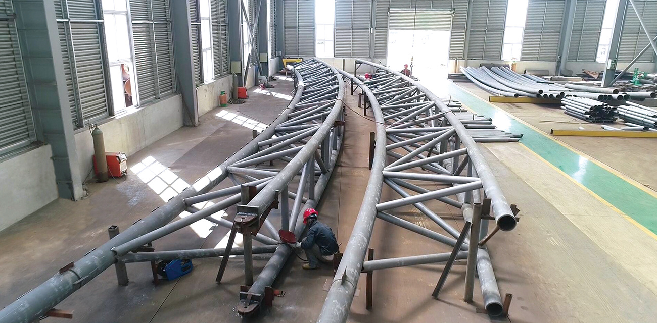
III. Mastering the Geometry: Types of Carbon Steel Pipe Bends
Our comprehensive product line covers every geometric necessity, from standard radius changes to highly specialized configurations. The primary distinction among these types lies in their radius-to-diameter ratio (), manufacturing method, and specific application purpose.
3.1 Radius Defined Bends (3D, 5D, and Long Radius)
The radius () of a pipe bend is the distance from the pipe’s centerline to the center of the bending arc. The designation or refers to the centerline radius expressed as a multiple of the nominal pipe diameter ().
- 3D Bends: Radius is . Offers a balance between space-saving and smooth flow. Common in process piping and smaller diameter applications.
- 5D Bends: Radius is . The industry standard for high-volume, long-distance pipelines (especially oil/gas) where piggability and minimal pressure drop are the priority. Often synonymous with Piggable Bends.
- Long Radius Bend: A general term encompassing all bends with . We regularly manufacture bends up to , and even higher, often referred to as Customized Bends.
3.2 Manufacturing Technique Defined Bends
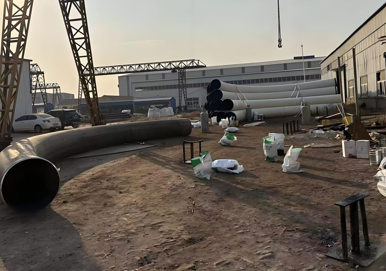
Hot Induction Bend (HIB)
This is our flagship and most technically advanced product. Induction Bends (or Hot Bend) are produced using the Hot Induction Bending process, detailed extensively in Section IV. This method offers unparalleled control over geometry and material properties.
Seamless Bend
Manufactured from seamless pipe, these bends are preferred for high-pressure, high-criticality applications where absolute homogeneity and the absence of a longitudinal weld seam are specified to maximize reliability.
Miter Bends
Unlike the smooth, continuous curve of an induction bend, a Miter Bend is fabricated by cutting and welding straight sections of pipe together at an angle to create the desired directional change. While structurally permissible under certain codes (like ASME B31.1 and B31.3) for low-pressure or non-critical lines, our primary focus is on Induction Bends due to their superior flow characteristics and higher integrity. However, we offer Miter Bends as a cost-effective alternative when specified.
I. Common Nominal Pipe Size (NPS) and Wall Thickness Parameters
The table below lists common pipe diameters and their corresponding standard Schedule wall thicknesses used in industry. These are the specifications of the parent pipe material utilized in our Hot Induction Bending process.
| Nominal Pipe Size (NPS) | Nominal Diameter (DN) | Outer Diameter (OD) (Inches / mm) | Schedule | Wall Thickness (WT) (Inches) | Wall Thickness (WT) (mm) |
| 4″ | Sch 40 (STD) | ||||
| Sch 80 (XS) | |||||
| 6″ | Sch 40 (STD) | ||||
| Sch 80 (XS) | |||||
| 8″ | Sch 40 (STD) | ||||
| Sch 80 (XS) | |||||
| Sch 160 | |||||
| 12″ | Sch 40 (STD) | ||||
| Sch 80 (XS) | |||||
| 16″ | Sch 40 (STD) | ||||
| Sch 80 | |||||
| 20″ | Sch 30 | ||||
| Sch 60 | |||||
| 24″ | Sch 40 | ||||
| Sch 80 | |||||
| 30″ | STD | ||||
| XS | |||||
| 36″ | STD | ||||
| Sch 80 | |||||
| 48″ | STD | ||||
| Custom |
II. Bend Radius () and Angle Parameters
The primary advantage of Hot Induction Bending is its flexibility in achieving various bending radii and angles, crucial for modern pipeline design and installation.
| Parameter Type | Common Range and Standards | Typical Application Name | Notes |
| Bend Radius () | (3D) | 3D Bends | Suitable for space-constrained lines that still require piggability. |
| (5D) | 5D Bends (Piggable Bends) | Industry standard for mainline transmission, ensuring optimal pig passage and minimal fluid resistance. | |
| Long Radius Bend | Used for ultra-long distance, high-pressure pipelines with stringent fluid dynamic requirements. | ||
| Bend Angle () | Customized Bend | We can manufacture bends at any angle, including (). | |
| Bend Geometry | Single Plane | Pipe Bends | Direction change confined to one geometric plane. |
| Multi-Plane | 3D Bends (Custom) | Bends changing direction in multiple planes, necessary for complex plant layouts. |
III. Manufacturing Tolerances and Wall Thickness Control
Quality in Hot Induction Bending is defined by strict adherence to dimensional and wall thickness tolerances. We comply rigorously with the industry standard ASME B16.49 and maintain even tighter internal tolerances on critical parameters.
| Tolerance Parameter | Industry Standard (ASME B16.49) | Our Internal Standard (Tighter) | Criticality |
| Maximum Wall Thinning | Ensures the required pressure rating is maintained at the bend extrados (outer curve). | ||
| Ovality (Out-of-Roundness) | Guarantees passage and minimizes flow turbulence. | ||
| Bend Angle Deviation | Ensures accurate fit-up during field installation and spool fabrication. | ||
| Tangent Length Deviation | Ensures precise alignment when connecting to straight pipe or flanges. |
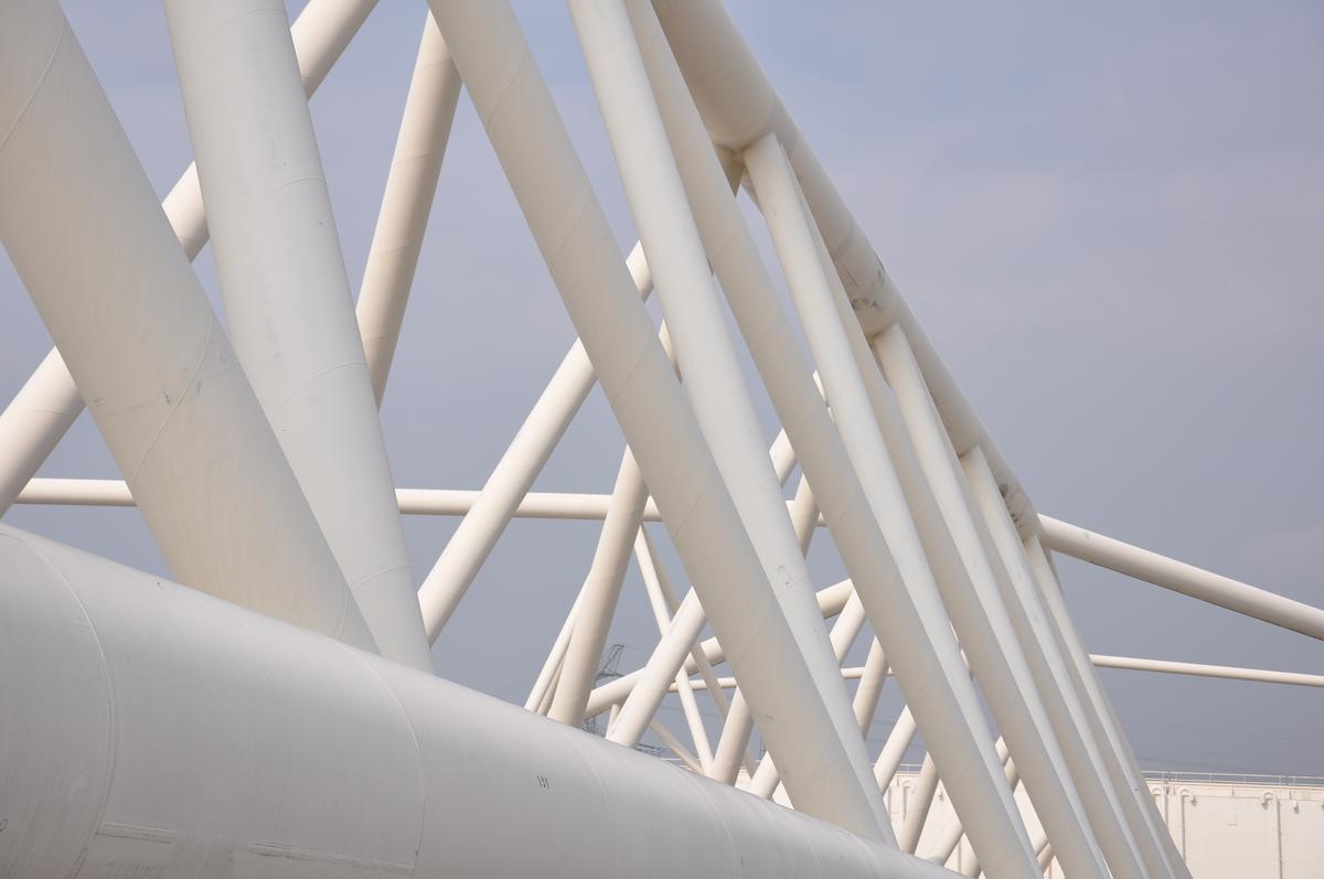
3.3 Specialized Configurations
- U Bend / J Bend: These complex, multi-plane bends are crucial in heat exchangers, boiler tubes, and furnace coils. The U Bend forms a return, while the J Bend is an asymmetrical, often customized, curve used for stress isolation or specific equipment connection. Their manufacture requires precise control over the entire bend profile to ensure dimensional accuracy for fitting into heat exchanger tube sheets.
- Short Bend: A relatively non-standard term, often used to denote a bend that is shorter than a typical long radius bend but still larger than a standard elbow (e.g., or ).
- Tube Bends / Bend Fittings: While ‘Pipe Bends’ typically refer to the full segment of a pipeline, ‘Tube Bends’ refer to smaller diameter or thinner wall sections often used in instrumentation, hydraulic, or boiler systems. ‘Bend Fittings’ is a generic term referring to the finished product as an identifiable component for connection.
IV. The Core Technology: Hot Induction Bending (HIB) Process
Our commitment to superior quality is centered on our advanced Hot Induction Bending (HIB) capability. This non-mandrel, localized heating technique is universally recognized as the best method for manufacturing high-quality, large-radius pipe bends.
4.1 Principle of Operation
- Clamping: A straight section of pipe is clamped into the HIB machine’s pivot arm.
- Induction Coil: A high-frequency induction coil is positioned around a narrow, annular section of the pipe, heating only this ring to the required plastic forming temperature (typically to for carbon steel).
- Forward Feeding: The pipe is continuously pushed forward through the coil at a controlled, slow rate by a hydraulic ram.
- Bending: As the heated ring exits the coil, the mechanical force from the pivot arm forces the pipe to bend around a fixed radius shoe.
- Quenching/Cooling: Simultaneously, the outside and inside of the bend are subjected to controlled cooling—often with water jets or air—to manage the metallurgical structure and maintain the desired mechanical properties.
4.2 Technical Advantages of HIB
The HIB process offers decisive advantages over traditional cold bending or mandrel bending:
- Superior Wall Thinning Control: The localized heating and controlled feed rate minimize wall thinning on the extrados (outer radius) and wall thickening on the intrados (inner radius). HIB allows for the tightest control over the cross-section, which is paramount for maintaining pressure ratings.
- Minimal Ovality: HIB produces an exceptionally consistent circular cross-section throughout the bend, crucial for piggability and structural integrity.
- Metallurgical Integrity: By controlling the peak temperature and cooling rate (a process known as quench and temper during the bend), we can maintain or even improve the mechanical properties of the high-strength WPHY and low-temperature WPL grades, preventing loss of yield strength or toughness.
- Variable Geometry: The setup allows us to change the angle, radius, and even the plane of the bend rapidly, enabling the production of Customized Bends and complex geometries.
V. Technical Parameters and Manufacturing Capabilities
Our facilities are equipped to handle a wide range of pipe diameters and wall thicknesses, ensuring we can meet the requirements of mainline transmission, distribution networks, and intricate process piping systems.
5.1 Dimensional and Geometric Capabilities
| Parameter | Metric Range | Imperial Range | Notes |
| Nominal Pipe Size (NPS) | Larger sizes available upon special inquiry. | ||
| Wall Thickness (WT) | Including schedules up to . | ||
| Bend Radius () | Long Radius Bend is standard; Short Bend and custom available. | ||
| Bend Angle () | Including () and (custom). |
5.2 Key Manufacturing Tolerances (ASME B16.49 and Project Specific)
Precision bending is defined by the strict control of dimensional tolerances. We adhere rigorously to the standards set by ASME B16.49 for Factory-Made Wrought Steel Buttwelding Induction Bends for Transport and Distribution Systems, as well as more stringent project-specific tolerances.
| Characteristic | ASME B16.49 Tolerance | Our Standard Goal | Importance |
| Ovality (Out-of-Roundness) | Critical for piggability and structural integrity. | ||
| Wall Thinning | Maintains pressure containment strength. | ||
| Tangential End Straightness | Ensures proper fit-up for field welding. | ||
| Angle Tolerance | Essential for spool and module fabrication alignment. |
VI. Quality Assurance, Inspection, and Certification
Quality control is integrated at every stage of our production, from raw material procurement to final packaging, ensuring that every pipe bend leaves our facility ready for immediate, critical service. Our system complies with ISO 9001 and industry-specific requirements like API Q1.
6.1 Non-Destructive Examination (NDE/NDT)
All pipe bends undergo mandatory and specified NDE to ensure internal and external integrity:
- Visual Examination (VT): inspection for surface defects, dimensional checks, and material stamps.
- Ultrasonic Testing (UT): Used for volumetric examination of the bend area, especially on high-thickness and high-pressure bends, to detect internal flaws and laminations.
- Magnetic Particle Testing (MT) / Liquid Penetrant Testing (PT): Applied to the entire surface to detect surface-breaking discontinuities or cracks introduced during the bending process.
- Radiographic Testing (RT): Used to examine the parent pipe weld seam (if applicable) and critical sections of the bend for volumetric defects.
6.2 Destructive and Mechanical Testing
For all heats and project-specific batches, mechanical tests are performed to confirm that the bending process has not adversely affected the material’s properties:
- Tensile Testing: To confirm Yield Strength, Tensile Strength, and Elongation meet the specified values (e.g., WPHY 70).
- Hardness Testing: To ensure the material is not excessively hardened, which could indicate cracking susceptibility or difficulty in field welding.
- Charpy V-Notch Impact Testing: Mandatory for all A420 WPL and other low-temperature grades, verifying toughness at specified design temperatures.
6.3 Post-Bend Heat Treatment (PBHT)
For certain materials (especially high-yield and low-temperature grades) and specific wall thicknesses, a Post-Weld Heat Treatment (PWHT) or Post-Bend Heat Treatment (PBHT) is required to relieve residual stresses induced by the bending process and restore optimum toughness and ductility. Our facility has precision-controlled furnaces to execute this critical step in accordance with ASME B31 codes and material standards.
VII. Applications Across Critical Industries
The robust design and verified performance of our Carbon Steel Pipe Bends make them indispensable across a spectrum of demanding industrial sectors:
7.1 Oil and Gas Transmission (Pipelines)
- Requirement: High-yield strength (WPHY 60, WPHY 70) for high-pressure, large-diameter transmission lines. Piggable Bends are universally required for mainline integrity management.
- Product Focus: and Induction Bends from seamless pipe to minimize risk.
7.2 Petrochemical and Chemical Processing
- Requirement: Compliance with strict process piping codes (ASME B31.3), high-temperature resistance, and corrosion allowance.
- Product Focus: ASTM A234 WPB and customized small-diameter bends for complex plant layouts.
7.3 Power Generation (Conventional and Nuclear)
- Requirement: Extremely high pressure and high temperature resistance (boiler feed water lines, steam lines).
- Product Focus: Thick-wall A234 WPB/WPC, and specialized U Bends and J Bends for boiler and heat exchanger systems to manage severe thermal cycling and stress.
7.4 LNG and Cryogenic Service
- Requirement: Guaranteed toughness at cryogenic temperatures.
- Product Focus: A420 WPL3 and A420 WPL6 Low Temperature Steel Pipe Bends, certified with impact testing.
VIII. Conclusion: Defining Excellence in Fluid Direction
The reliable performance of a pipeline system hinges on the quality of its components. Our Carbon Steel Pipe Bends are designed not merely to meet specifications but to exceed the operational expectations of the world’s most critical infrastructure projects.
By integrating an extensive materials portfolio—from the ubiquitous A234 WPB to the ultra-high strength WPHY 70 and the specialized A420 WPL6—with the technological superiority of Hot Induction Bending, we deliver products that ensure flow efficiency, structural integrity, and long-term maintainability (piggability).
We are more than a manufacturer; we are an engineering partner committed to providing reliable, custom-engineered solutions for any challenge in fluid conveyance. Our rigorous quality control, adherence to global standards, and dedication to technical precision guarantee that when you specify our pipe bends, you are specifying uncompromising reliability for the backbone of your industrial operations.
We invite you to partner with us to ensure the success and longevity of your next critical piping project.
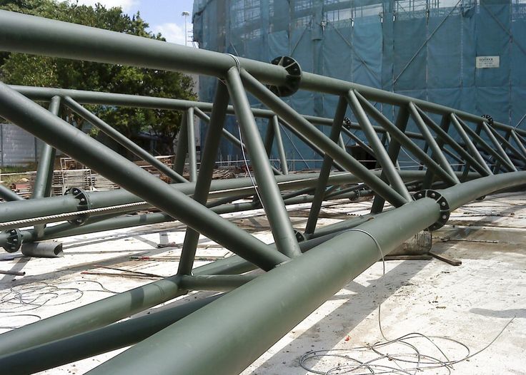
In the realm of construction, finding the right structural solution is crucial for ensuring the safety, strength, and efficiency of a building. One such versatile and reliable option gaining popularity in recent years is the use of pipe trusses. These trusses, constructed from interconnected pipes, offer numerous advantages in terms of strength, flexibility, and cost-effectiveness. In this article, we will explore the concept of pipe trusses, their applications, and the benefits they bring to construction projects.
Advantages of Tubular Truss Steel Structure: Compared with space truss structure, pipe truss structure eliminates vertical bar and space truss bottom chord node, which can meet the requirements of various architectural forms, especially arch and arbitrary curved shape construction is more advantageous than space truss structure. Its stability is different and material consumption is saved. The steel pipe truss structure is developed on the basis of lattice structure, which has its unique superiority and practicality compared with lattice structure. The steel self-weight of the structure is more economical. Compared with traditional open section (H-steel and I-steel), the steel truss pipe truss structure section material is evenly distributed around the neutral axis, and the section has good compressive and bending bearing capacity and large stiffness at the same time. There is no node plate, the structure is simple, and the most important thing of the pipe truss structure is that it is beautiful, easy to shape and has certain decorative effect. The overall performance of the pipe truss structure is good, torsional stiffness is large, beautiful and generous, easy to make, install, flip, hoist; using cold-bent thin-walled steel pipe truss, light weight, good rigidity, save steel structure, and can fully play Read more
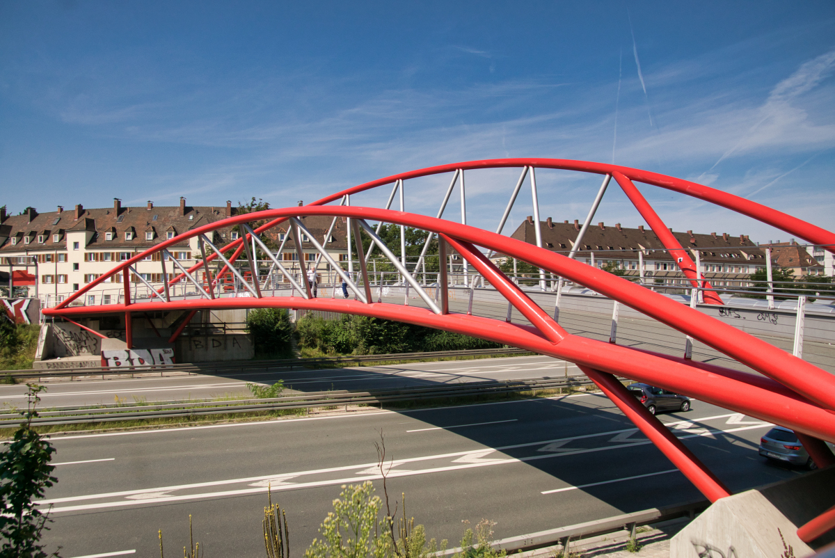
Roofing Systems: Pipe trusses are commonly used as roofing systems in commercial, industrial, and even residential buildings. The triangular or quadrilateral shape of the trusses provides excellent load-bearing capacity, allowing for large spans without the need for intermediate supports. This design feature creates expansive interior spaces and facilitates efficient use of the building.
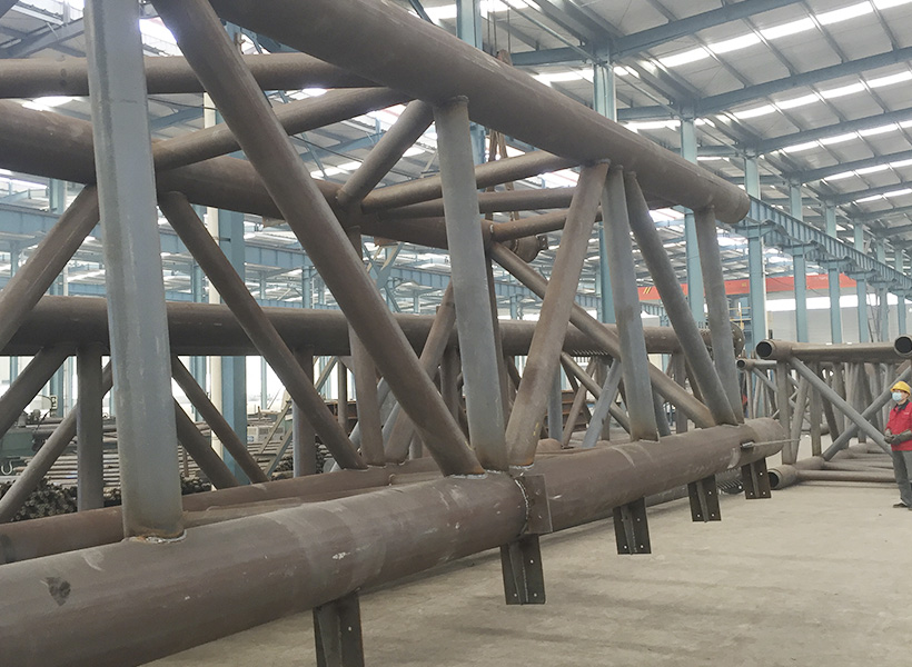
Pipe trusses, also known as tubular trusses, are structural frameworks composed of interconnected pipes. These trusses form a triangular or quadrilateral shape to provide stability and distribute loads evenly, allowing for the construction of large and complex structures. The pipes used in pipe trusses are typically made of steel or aluminum due to their high strength-to-weight ratio and durability.
These Aluminum Bolt Square Truss are always used as background frame and for light lighting .Connect each truss with pin part and easy to set up .Length or thickness can be customized according to customer's requirement. Truss Material Aluminum alloy 6082-T6 Light duty truss 200*200mm 220*220mm Medium duty truss 290*290mm 300*300mm 350*350mm 400*400mm 450*450mm 400*600mm Heavy duty truss 520*760mm 600*760mm 600*1100mm Main tube thickness Ø30*2mm Ø50*3mm Ø50*4mm Vice tube thickness Ø20*2mm Ø25*2mm Ø30*2mm Brace tube thickness Ø20*2mm Ø25*2mm Ø30*2mm Truss length 0.5m / 1m / 1.5m / 2m / 3m / 4m or customized Truss type Spigot or Bolt Truss shape Ladder , Triangular, Square, Rectangle,Arc, Circle,irregular shapes Optional color Silver / Black / Blue or customized Application Booth, fashion show, catwalk, wedding, new product release, concert, ceremony, party, etc. Delivery time 5-15 days 300mm x 300mm Spigot Truss Load Table Span (M) 2M 3M 4M 5M 6M 8M 10M 12M 14M Center Point Load (KGS) 890 780 680 600 470 390 290 210 160 Deflection (MM) 5 8 13 13 16 29 45 62 88 DistributeLoad (KGS) 1630 1530 1430 1330 1230 930 730 630 530 Deflection (MM) 4 12 23 36 48 75 97 138 165 400mm Read more
Large Span Prefabricated Building Metal Frame Shed Warehouse Steel Structure ,Steel material Structural steel Q235B, Q345B, or others as buyers' requests. Purlin C or Z purlin: Size from C120~C320, Z100~Z20 Bracing X-type or other type bracing made from angle, round pipe
