Industrial Filtration Engineering
Heavy-Duty Stainless Steel Wedge Wire Screen Pipe
Precision-Engineered Continuous-Slot Vee-Wire® Filter Cylinders for High-Pressure Sand Control, Petrochemical Processing, and Industrial Liquid-Solid Separation. Manufactured in Compliance with ASTM A269 / A312 / 304 / 316 / A497 Standards.
Slot Tolerances: ±0.005 mm (10 µm)
Full-Wound Fusion Welding
01
System Architecture & Fundamental Engineering Mechanics
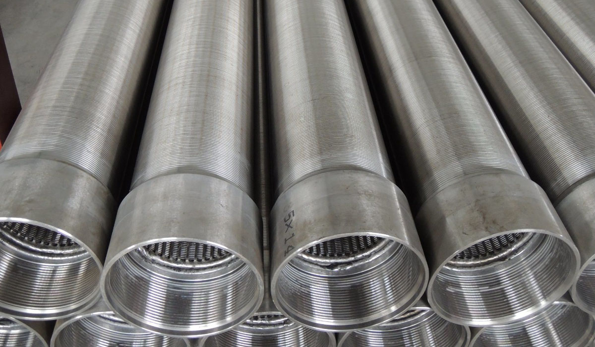
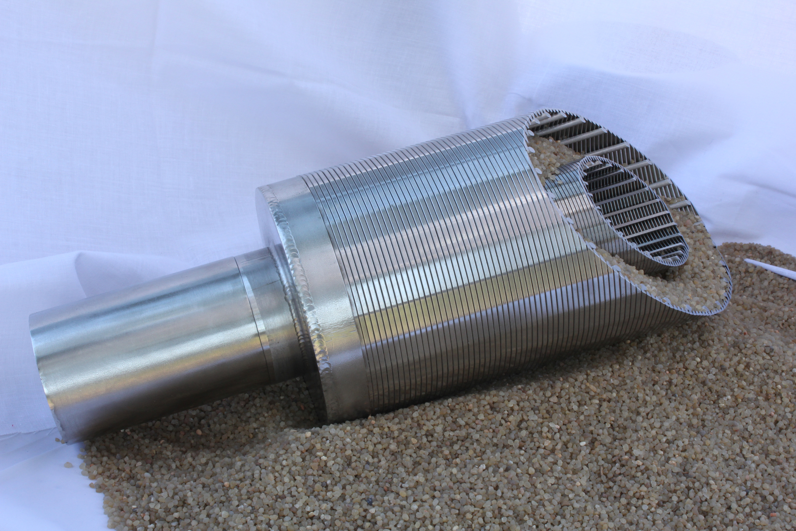
The Stainless Steel Wedge Wire Screen Pipe (also commercially recognized as continuous-slot Vee-Wire® screen cylinders or profile wire filter pipes) represents an advanced filtration geometry designed specifically to address severe fluid dynamics, high mechanical stresses, and aggressive chemical environments. Unlike conventional perforated, slotted, or mesh-wrapped strainers, the wedge wire profile pipe is manufactured using a specialized, automated resistance fusion welding process. Cold-rolled surface profile wires—typically triangular or trapezoidal in cross-section—are continuously wrapped in a helical structure around an internal cylindrical array of longitudinal support profiles. Every single intersection between the surface profile wire and the underlying support rod is metallurgically joined via high-frequency resistance welding.
This geometric arrangement creates a unique two-dimensional expanding slot aperture. The wedge-shaped wire is oriented such that its narrowest width faces outward toward the oncoming fluid flow, while the widest section of the wedge forms the inner wall of the slot aperture. This creates a non-clogging V-shaped profile that widens inward. Consequently, any particle that manages to pass through the initial exterior entry slot will freely traverse through the remainder of the screen element without becoming wedged or bridging across the opening—a critical advantage over parallel-walled slotted pipes or multi-layered woven wire meshes.
Structural Advantages of Continuous Vee-Wire Construction:
- Non-Clogging Slot Dynamics: The V-shaped aperture profile reduces surface friction and prevents particle entrapment, significantly reducing backwash frequency and field maintenance requirements.
- High-Strength Monolithic Integrity: 360-degree continuous resistance welding delivers exceptional hoop strength, torsional resistance, and high collapse strength ratings capable of withstanding deep formation pressure differentials (>120 BAR).
- Maximized Hydrodynamic Open Area: Eliminates blind spots and dead zones, permitting higher flow rates while maintaining ultra-low entrance velocities to prevent fluid jet erosion and screen scale formation.
02
Metallurgical & Chemical Composition Standards
The selection of the optimal alloy grade is vital to extending the service lifetime of wedge wire filter pipes operating in hostile environments such as sour gas wells, high-salinity geothermal aquifers, and aggressive chemical process streams. Below is the precise chemical elemental matrix for our primary manufacturing alloys compliant with ASTM, UNS, and DIN standards.
| Grade / Alloy | UNS Designation | Carbon (C) % | Chromium (Cr) % | Nickel (Ni) % | Molybdenum (Mo) % | Nitrogen / Titanium | PREN Value |
|---|---|---|---|---|---|---|---|
| AISI 304 | S30400 | ≤ 0.08 | 18.0 – 20.0 | 8.0 – 10.5 | – | N ≤ 0.10 | ~ 19.0 |
| AISI 304L | S30403 | ≤ 0.03 | 18.0 – 20.0 | 8.0 – 12.0 | – | N ≤ 0.10 | ~ 19.0 |
| AISI 316 | S31600 | ≤ 0.08 | 16.0 – 18.0 | 10.0 – 14.0 | 2.0 – 2.5 | N ≤ 0.10 | ~ 25.0 |
| AISI 316L | S31603 | ≤ 0.03 | 16.0 – 18.0 | 10.0 – 14.0 | 2.0 – 3.0 | N ≤ 0.10 | ~ 25.0 |
| AISI 321 | S32100 | ≤ 0.08 | 17.0 – 19.0 | 9.0 – 12.0 | – | Ti 5x(C+N) min | ~ 20.0 |
| Duplex 2205 | S31803 / S32205 | ≤ 0.03 | 22.0 – 23.0 | 4.5 – 6.5 | 3.0 – 3.5 | N 0.14 – 0.20 | ≥ 35.0 |
| Hastelloy C276 | N10276 | ≤ 0.01 | 14.5 – 16.5 | Balance | 15.0 – 17.0 | W 3.0 – 4.5 | > 65.0 |
03
Mechanical Properties & Physical Metrics
Mechanical integrity is paramount when wedge wire pipes are deployed as primary sand control screens in deep water wells, offshore oil platforms, or heavy industrial pressure vessels. Cold working during profile wire drawing enhances physical tensile yields, providing higher mechanical resistance without sacrificing ductility.
| Alloy Type | Tensile Strength (MPa) | Yield Strength 0.2% Proof (MPa) | Elongation A5 (%) | Hardness (Rockwell B) | Density (g/cm³) | Thermal Expansion (10⁻⁶/K) |
|---|---|---|---|---|---|---|
| SS 304 / 304L | 520 – 720 | ≥ 210 | ≥ 45 | 70 – 85 HRB | 7.93 | 17.2 |
| SS 316 / 316L | 540 – 740 | ≥ 220 | ≥ 40 | 75 – 90 HRB | 7.98 | 16.5 |
| SS 321 | 520 – 700 | ≥ 205 | ≥ 40 | 70 – 88 HRB | 7.92 | 16.6 |
| Duplex 2205 | 650 – 880 | ≥ 450 | ≥ 25 | 25 – 32 HRC | 7.80 | 13.7 |
04
Comprehensive Dimensional & Structural Load Master Specifications
The operational safety and structural collapse resistance of continuous-slot wedge wire screens are direct functions of wire profile geometry, support rod spacing, and rod cross-sectional mass. The data table below details standard industry configurations, corresponding collapse pressures, tensile capacities, and wire/rod profile ratios.
| Nom. Size (Inch) | Outer Diameter (mm) | Slot Width (mm) | Standard Length (m) | Collapse Strength (BAR) | Tensile Load Capacity (Tons) | Surface Wrap Wire Profile (W×H mm) | Support Rod Specs (Dia/Qty) |
|---|---|---|---|---|---|---|---|
| 3-1/2″ | 88.9 | 1.00 | 3.0 | > 22 | 10.2 | 2.3 × 3.5 | 3.8 mm / 22 rods |
| 4-1/2″ | 114.3 | 1.00 | 3.0 | > 28 | 11.5 | 2.3 × 3.5 | 3.8 mm / 22 rods |
| 6-5/8″ Standard | 168.3 | 0.75 | 5.8 | > 40 | 12.8 | 2.3 × 3.5 | 3.8 mm / 32 rods |
| 6-5/8″ Standard | 168.3 | 1.00 | 5.8 | > 33 | 12.8 | 2.3 × 3.5 | 3.8 mm / 32 rods |
| 6-5/8″ Heavy Duty | 168.3 | 0.63 | 5.8 | > 83 | 45.0 | 3.2 × 6.0 | 6.0 mm / 32 rods |
| 8-5/8″ Light | 219.1 | 1.00 | 5.8 | > 34 | 21.9 | 2.3 × 3.5 | 3.8 mm / 48 rods |
| 8-5/8″ Medium | 219.1 | 1.00 | 5.8 | > 50 | 38.2 | 3.0 × 5.0 | 4.0 mm / 48 rods |
| 8-5/8″ Heavy Duty | 219.1 | 1.00 | 5.8 | > 60 | 46.0 | 3.2 × 6.0 | 5.0 mm / 48 rods |
| 10-3/4″ Standard | 273.1 | 0.75 | 5.8 | > 50 | 32.9 | 2.3 × 3.5 | 4.9 mm / 55 rods |
| 10-3/4″ Medium | 273.1 | 1.00 | 5.8 | > 60 | 39.5 | 3.0 × 5.0 | 4.9 mm / 55 rods |
| 10-3/4″ Extra Heavy | 273.1 | 1.00 | 5.8 | > 100 | 48.0 | 3.2 × 6.0 | 5.0 mm / 55 rods |
| 12-3/4″ Heavy Duty | 323.9 | 1.00 | 5.8 | > 120 | 37.2 | 3.0 × 5.0 | 4.0 mm / 50 rods |
| 14″ Large Diameter | 355.6 | 1.00 | 3.0 | > 80 | 37.8 | 3.0 × 5.0 | 4.0 mm / 59 rods |
05
Profile Wire Specifications & Hydrodynamic Profiles
The operational performance of a wedge wire screen pipe depends on selecting the precise balance between wire dimensions and support rod structure. The cross-sectional width and height of the surface wrap wire govern the open area percentage and particle retention ability, whereas the longitudinal support rods establish the collapse threshold against high differential pressures.
Standard Surface Wrap Wires
- 10Db Wire: Width 0.76mm × Height 1.50mm
- 20Db Wire: Width 1.20mm × Height 2.30mm
- 120 Wire: Width 1.50mm × Height 2.50mm
- 130 Wire: Width 1.80mm × Height 4.50mm
- 60 Wire: Width 2.20mm × Height 3.50mm
- 90 Wire: Width 3.20mm × Height 6.00mm
Internal Support Profile Geometry
- Vee-Shape Wire Rods: Highly flexible flow dynamics
- Round Rods: Standard economical multi-purpose strainers
- Flat Bar Strip Rods: High axial tensile strength
- Teardrop Profiles: Reduced pressure drop performance
- Heavy Structural Channels: Ultra-deep well collapse support
- Custom Milled Support Bars: Extreme duty pressure vessels
06
Direction of Filtration (Flow Dynamics Orientation)
Depending on the specific orientation of the surface profile wire relative to the support rods and the fluid pathway, wedge wire screen pipes are classified into distinct filtration flow configurations. Selecting the appropriate flow geometry ensures optimal cleaning efficiency, scrapers clearance, and backwashing cycles.
| Type Acronym | Flow Direction Designation | Structural Arrangement | Primary Industrial Applications |
|---|---|---|---|
| FOTI | From Outside To Inside | Surface profile wire wrapped around axial internal support rods. Flat side of surface wire faces outward. | Water well screens, oil production wells, external pressure filter cartridges, intake strainers. |
| FITO | From Inside To Outside | Surface wire located inside the cylinder, welded to external axial support rods. Smooth inner surface. | Internal screw press dewatering systems, internal scraper filters, continuous centrifuge baskets. |
| SIFOTI | Slot Internal From Outside To Inside | Axial profile wires aligned longitudinally inside external circumferential ring supports. Axial slots. | High-viscosity starch separation, pulp and paper fractionation, specialized distributor headers. |
| SIFITO | Slot Internal From Inside To Outside | Axial profile wires aligned longitudinally along the outside of internal ring supports. Axial slot orientation. | Rotary drum screens, trommel screen cylinders, internal axial flow catalyst retainers. |
07
State-of-the-Art Automated Production Methodology
Our facility utilizes specialized CNC automated resistance welding lathes designed specifically for high-precision profile wire continuous winding. The manufacturing process is subjected to computer-controlled real-time sensor feedback to maintain dimensional precision down to the micron level across standard 6-meter manufacturing lengths.
1. Precision Cold Rolling
Round raw wire stock is cold-rolled through precision carbide dies to form the exact triangular Vee-profile with smooth surface finishes and tensile strength.
2. High-Frequency Fusion
As the wire wraps spirally around support rods, high-frequency electric resistance weld pulses fuse every intersection point without filler material.
3. CNC Optical Slot Verification
Laser sensors continuously measure slot openings during winding, dynamically adjusting feed rates to maintain tolerances as tight as ±0.005 mm.
4. End Fitting Fabrication
Automated TIG/MIG welding units attach customized weld rings, ANSI flanges, or threaded couplings under strict WPS/PQR welding parameters.
08
Customized End Fittings & Joint Interface Systems
To ensure smooth integration into existing piping manifolds, well casing strings, or pressure vessel housings, we offer a comprehensive suite of standardized and engineered end fittings. All joints are fully welded and tested for tensile integrity.
| Fitting Configuration | Standard Engineering Specifications | Operational Features & Benefits |
|---|---|---|
| Beveled Weld Rings | 30° to 37.5° bevel angles matching ASME B16.25 standards for circumferential butt-welding. | Provides maximum joint strength equal to screen body; ideal for deep permanent well casings. |
| ANSI / DIN Flanges | Class 150, 300, 600, or PN10-PN40 Slip-On, Weld Neck, or Blind Flange standards. | Allows fast bolt-on installation and removal during scheduled vessel maintenance turnarounds. |
| API Threaded Couplings | Male x Female API 5CT LTC, STC, BTC, or NPT / BSPT threaded connection profiles. | Enables direct coupling to standard drill pipe strings and oil/gas casing production tubing. |
| Quick-Release Clamp Ring | Sanitary Tri-Clamp / ISO-K style grooved collars with elastomeric O-ring seals. | Designed for high-purity food, beverage, and pharmaceutical processing lines requiring rapid CIP cleaning. |
Hydraulic Performance Optimization
Open Area Calculation & Hydraulic Efficiency Fluid Dynamics
The open area percentage of a continuous-slot wedge wire screen pipe determines its hydraulic efficiency, pressure drop ($\Delta P$), and fluid entrance velocity. Unlike perforated pipes where open area rarely exceeds 15% to 20%, wedge wire screen pipes can achieve up to 65% open area while maintaining structural rigidity.
By maintaining low fluid entrance velocities (typically below 0.15 m/s or 0.5 ft/s), heavy mineral precipitation, incrustation, and local fluid turbulence are minimized. This significantly reduces long-term pumping energy consumption and prevents pump cavitation.
09
Hydraulic Flow Capacity Matrix (Water Well Applications)
The table below highlights flow throughput metrics for standard screen pipe diameters operating at a conservative inlet entrance velocity of 0.03 m/s (0.1 ft/s), demonstrating the superior discharge volumes achieved via continuous slot design.
| Screen Size (OD) | Slot Opening (mm) | Open Area (%) | Flow Rate per Meter (m³/hr) | Flow Rate per Meter (GPM) | Recommended Aquifer Grain Size |
|---|---|---|---|---|---|
| 114.3 mm (4.5″) | 0.25 mm | 9.8 % | 3.8 m³/h | 16.7 GPM | 0.30 – 0.60 mm (Fine Sand) |
| 114.3 mm (4.5″) | 0.50 mm | 17.8 % | 6.9 m³/h | 30.3 GPM | 0.60 – 1.18 mm (Medium Sand) |
| 168.3 mm (6.625″) | 0.50 mm | 17.8 % | 10.1 m³/h | 44.5 GPM | 0.60 – 1.18 mm (Medium Sand) |
| 168.3 mm (6.625″) | 1.00 mm | 30.3 % | 17.2 m³/h | 75.7 GPM | 1.18 – 2.36 mm (Coarse Sand) |
| 219.1 mm (8.625″) | 0.75 mm | 24.5 % | 18.2 m³/h | 80.1 GPM | 0.85 – 1.70 mm (Coarse Sand) |
| 219.1 mm (8.625″) | 1.00 mm | 30.3 % | 22.5 m³/h | 99.1 GPM | 1.18 – 2.36 mm (Coarse Sand) |
| 273.1 mm (10.75″) | 1.00 mm | 30.3 % | 28.1 m³/h | 123.7 GPM | 1.18 – 2.36 mm (Coarse Sand) |
| 323.9 mm (12.75″) | 1.50 mm | 39.5 % | 43.4 m³/h | 191.1 GPM | 2.00 – 4.75 mm (Gravel Pack) |
10
Surface Finishing, Chemical Passivation & Corrosion Prevention
Resistance welded stainless steel wedge wire components undergo rigorous surface cleaning to remove free iron particles, heat tint oxides, and shop contaminants accumulated during cold rolling and high-frequency welding. Chemical pickling and electropolishing ensure the formation of a passive chromium-oxide layer ($Cr_2O_3$).
Acid Pickling & Chemical Passivation
Immersion in a controlled nitric-hydrofluoric acid bath ($HNO_3 / HF$) chemically dissolves embedded iron tramp metals and restores the passive chromium oxide film in accordance with ASTM A380 and ASTM A967 standards.
Electro-Chemical Polishing
Anodic dissolution in an electrolyte bath reduces micro-roughness ($Ra < 0.2 \, \mu m$). Electropolishing eliminates micro-burrs along slot edges, drastically reducing bacterial bio-fouling and chemical scaling.
Physical Vapor Deposition / Coating
For hyper-saline geothermal brine wells or abrasive slurry mining operations, screen pipes can be upgraded with specialized ceramic, PTFE, or tungsten carbide wear coatings.
11
Quality Assurance Protocol & Inspection Standards
Every production run of stainless steel wedge wire screen pipes undergoes comprehensive NDT (Non-Destructive Testing) and dimensional verification protocol before release. Material Test Reports (MTR) according to EN 10204 3.1 are supplied with all shipments.
| Testing Category | Inspection Procedure / Standard | Acceptance Threshold Criteria |
|---|---|---|
| Slot Aperture Verification | Optical Projection & Feeler Gauge Inspection | ±0.015 mm for slots ≥ 0.10 mm; ±0.005 mm for ultra-fine slots. |
| Collapse Load Testing | Hydrostatic Pressure Chamber Verification | 100% of theoretical calculated yield limit without plastic deformation. |
| Weld Integrity Inspection | Dye Penetrant Testing (PT) / Ultrasonic | Zero surface-breaking cracks, lack of fusion, or inclusions per ASME VIII. |
| Roundness & Ovality | Laser Micrometer Full-Length Scan | Ovality variance within < 0.5% of nominal outer diameter. |
| Chemical Composition | Positive Material Identification (XRF-PMI) | 100% confirmation of elemental chemistry matching ASTM standards. |
12
Sector-Specific Industrial Applications
Due to their combination of high mechanical strength, corrosion resistance, and self-cleaning performance, continuous slot wedge wire screen pipes are utilized across vital process industries worldwide.
1. Groundwater Development & Geothermal Wells
Used as primary downhole sand screens in municipal water supply wells, agricultural irrigation wells, and high-temperature geothermal energy extraction systems. Controls formation sand, prevents drawdown, and protects submersible turbine pumps from impellor erosion.
2. Petrochemical & Oil/Gas Refining
Serves as catalyst support grids, center pipes, outer baskets, and scale traps in hydrotreating reactors, catalytic reformers, and molecular sieves. Withstands high thermal cycles and corrosive hydrocarbon fractions.
3. Sugar, Starch & Food Processing
Deployed in rotary juice strainers, corn wet-milling starch screens, sugar centrifugal baskets, and brewery mash tun false bottoms. Provides high sanitary standards and easy clean-in-place (CIP) characteristics.
4. Pulp & Paper Dewatering Systems
Integrated into pressure screens, knotters, and fiber fractionation equipment to remove contaminants and sort pulp fibers by length, operating under high dynamic pressure differentials and abrasive conditions.
13
Industrial Application Operational Parameters Matrix
| Industry Sector | Recommended Material | Typical Slot Range | Flow Orientation | Key Performance Target |
|---|---|---|---|---|
| Water Drilling | 304 / 304L / 316L | 0.25 mm – 1.50 mm | FOTI | Sand control, low drawdown velocity |
| Oil & Gas Wells | 316L / Duplex 2205 | 0.15 mm – 0.50 mm | FOTI | High collapse resistance, $H_2S$ immunity |
| Chemical Processing | 316L / Hastelloy C276 | 0.05 mm – 0.50 mm | FOTI / FITO | Corrosion resistance, precise particle cut-off |
| Pulp & Paper | 316L / Duplex 2205 | 0.10 mm – 0.35 mm | SIFOTI / FITO | Wear resistance under abrasive slurry conditions |
| Food & Beverage | 304 / 316L (Electropolished) | 0.20 mm – 1.00 mm | FITO | Sanitary smooth finish, rapid cleanability |
14
Field Installation Engineering & Best Practices
Proper installation procedures are essential to maintain slot geometry and prevent localized bending or structural buckling during well lowerings or pressure vessel installations.
1. Handling & Rigging Precautions
Always use wide nylon lifting slings rather than steel cables or chains to prevent crushing or scratching the precision surface profile wires. Avoid dragging screen pipes over rough surfaces.
2. Centralizer Placement in Well Boreholes
Install non-metallic or stainless steel casing centralizers every 3 to 6 meters along the screen length. Centralization ensures an even circumferential distribution of the surrounding gravel pack envelope and prevents direct contact with the borehole wall.
3. Field Joint Welding Guidelines
When butt-welding bevelled rings on-site, use GTAW (TIG) welding with argon shielding gas to prevent internal oxidation (“sugaring”). Match filler metals precisely (e.g., ER316L filler for 316L screen pipes).
15
Global Export Packaging & Heavy Logistics Standards
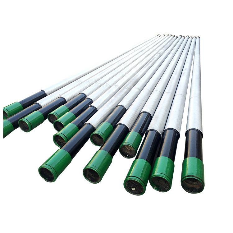
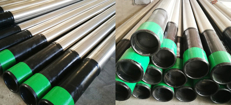
To ensure that continuous slot wedge wire screen pipes arrive on site with zero slot deformation or surface damage, our logistics department utilizes robust ISPM-15 compliant export packaging protocols.
Individual Protective Sleeve Wrapping
Each individual screen pipe is encased in heavy-duty bubble wrap and thermal shrink-sleeve film to isolate slot surfaces from dust, moisture, and mechanical abrasion.
Wooden Crate Enclosures
Heavy-duty IPPC heat-treated wooden boxes reinforced with internal wooden saddles prevent movement, flexing, or impact during multi-modal ocean and overland freight.
End Cap & Thread Protection
All threaded ends and bevelled weld rings are equipped with heavy-duty composite metal-plastic thread protectors or rubber end rings to absorb mechanical shocks during handling.
Need Custom Screen Pipe Technical Engineering Assistance?
Our engineering team can calculate collapse requirements, select optimal slot openings based on sand sieve analysis, and prepare tailored CAD drawings for your industrial project.
“`